Thank you all for having taken the time to read my post and share your thoughts. Very interesting insights.
First, yes, water unit weight = 62.4 pcf = 1,000 Kg/m
3
I think things have started to come together now. A few rough edges, though, mostly due to my illiteracy in geotechnics and the complexity of the structure.
For me this subject boils down to understanding how the whole system works so as to develop an abstracted physical model and eventually apply the necessary math to sustain it. Ultimately it will help me to decide whether this construction methodology scales up to be applied in larger tanks or not. This is a geotech problem, not a structural one, I think.
For radii up to 15m (50ft) and depths up to 3m (10ft) there's no need to do any fine-grained analysis or calculations. The system just works.
My boss, however, has the habit of calling me whenever he needs to extend and utilize this same system in bigger tanks, that is, R > 15m or H > 3m. From my experience, I can say that the larger tanks are less tolerant to flaws in the backfill than the smaller ones. I need to understand how this thing works intimately so that I can give him a qualified authoritative answer (and design) instead of an opinionated perception of how I think things work or should be done.
Passive pressure, by definition, implies a mobilizing action on the soil mass. Concrete in general, and these walls in particular, admit very small positive strains (and their corresponding tension stresses). As a result, I think it is rare that the associated displacement -in the form of an increase in radius- can trigger mobilization of the soil mass. This, plus the sub-optimal steel/concrete ratio used in the standard walls makes me think that the analysis of these tanks must be done within the
at-rest + compaction pressures domain (emphasis on compaction) as the soil never becomes aware of anything pushing into it. If it weren't like that, by the time the radial swelling derived from the hydrostatic pressure becomes significant, the wall will have cracked severely. I have verified that this is not the case when the backfill is properly executed. In such cases, the uncracked state of the thin walls is a strong indication of the pro-active role of the sloping backfill, such that:
[ul square]
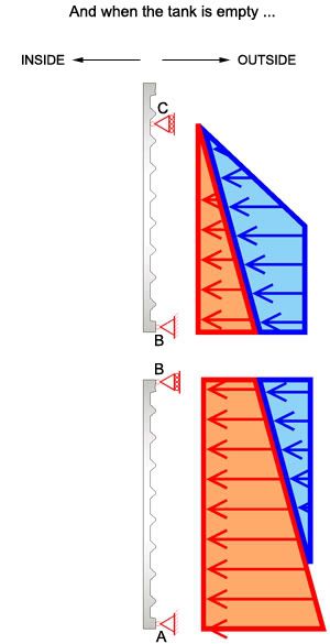
[li]when the tank is empty, the circular concrete shell is fully compressed (this configures the most severe condition during the tank's lifetime).[/li]
[li]when the tank is filled, the circular concrete shell either has a residual compression or, at most, a very very small tension.[/li]
[/ul]
That, however, is very difficult to prove and even harder to guarantee in practice, especially in the context of larger tanks (R > 15m or H > 3m). Besides height, radius and support conditions, which are the well known factors driving the tension derived from hoop force & bending moments, and consequently the compression that the soil buttress will be "expected" to provide, there are so many construction unknowns such as soil types, moisture content, slope steepness, contractors, equipment, labor, etc. that makes it difficult to accurately predict how much residual compression the walls will have at the full/empty conditions.
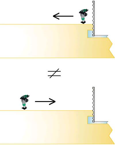
Add to that the compaction techniques. Each contractor seems to have its own
sui generis way of doing compaction. E.g. How each lift is effectively compacted by the rubber-tyre rollers and rammers makes a difference. Is it carried out from the wall outwards or viceversa?. It's not the same. Neither are the resulting pressures on the wall. And that's just one out of many variables.
Then we have rain. How sensitive is the backfill's performance to a heavy rain? Yet another potential headache.
It might seem that I've almost aggressively put the backfill buttress under the magnifying glass here. It is so because of its fundamental role in the stability of the whole system. Like I said above, it's a geotech problem after all. The standard thin concrete wall panels act as a mere liner. They contribute very little stiffness to the whole picture, so to say. (See the photo of a severely damaged tank in my previous post in which the backfill on the upper 4 ft of the wall is missing). In most "normal" projects involving tanks the approach is quite the opposite. The design of the wall (concrete + steel areas) is the primary focus and is designed based on a myriad of other variables. Backfill being just one of them. Its effect is conservatively guesstimated and that's it. Here, I have to demonstrate that with ordinary wall panels + a sloping backfill a safe, durable and stable large tank (R > 15m or H > 3m) is possible.
Codes as well as specialized literature from ACI, PCI (Precast Prestressed Concrete Institute) and PCA (Portland Cement Association) set the basis for tank design. Most notably, they introduce a sanitary coefficient (1.65) and a load factor (1.7). They also make it clear that the effect of backfill should not be taken into account when it is beneficial in counteracting fluid pressure. The rationale, as it has been said, is that leak tests must be done before applying the backfill. Imagine if I had the freedom to design according to those guidelines...things would be much easier (I and my license would be thankful).
Now, to shape things and tie loose ends:
fattdad said:
I would guess your sloping at-rest earth pressure would be on the order of 45 to 50 pcf...
If we assume the soil's equivalent fluid weight = 50 pcf = 802 Kg/m
3, then, does it mean that it will handle 80% of the hydrostatic pressure ? If so, the reinforcement will have to deal with the remaining 20%, won't it? I've done the calculations and the steel area needed to deal with 20% of the hydrostatic pressure is higher than the actual steel that's been used in these precast panels for decades. This sort of confirms my previous speculation in the sense that there must be a larger external pressure from the backfill acting on the wall. Maybe if we add the compaction surcharge to these 50 pcf we could fully compensate the hydrostatic pressure and even get some precious residual compression, right ?
Steel wouldn't be the problem eventually. I could embed bigger bars in the ribs of the panel and deal with the difference.
However, considering there cannot be any tension in the walls for the reasons exposed earlier, and despite all the soil-related uncertainties (also mentioned above) the common denominator is that most tanks in service today -even those with sub-optimal reinforcement- perform well and don't leak. Granted! those tanks are short, R < 15m or H < 3m.
What I'd like, as I said above, is to outline a reliable model that validates all these things. And most importantly it should protect me from liability in case things go wrong. And yes, I've seen a few projects, most notably those involving large rectangular tanks, gone totally wrong after a heavy rain caught them empty. Apparently the soil's Liquid Limit went overboard and so did the horizontal pressures...needless to say, collapse followed. Although I wasn't involved in any of them, they really raised awareness that these things are not to be taken lightly. As tanks approach R = 15m or H = 3m there begins to be a faint line that divides a fully functional structure from a collapsible one. If the wall panels are all the same, then success or failure depends exclusively on the characteristics of backfill and how it is carried out.
I'm totally aware that although the stability of these tanks is acceptable (R < 15m or H < 3m), their safety coefficient is 1.00 at best. They have no strength reserve. Period. Even more, they're very sensitive to many imponderable soil-related things and as such I don't want to be held responsible for a concept I didn't even conceive.
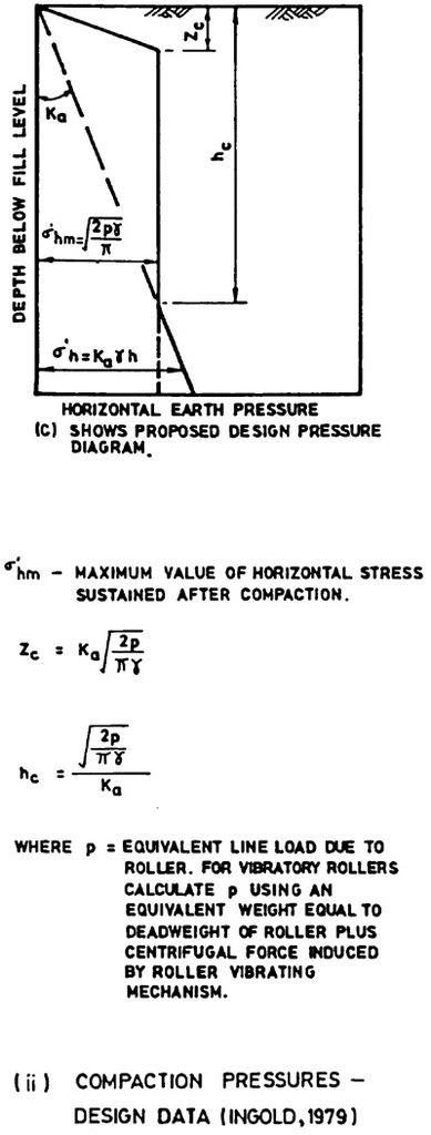
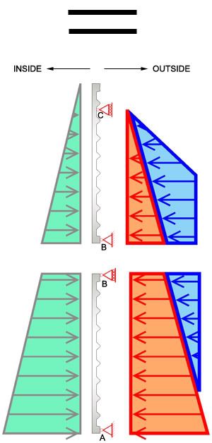
I think, generally speaking, what might be happening here is that I have a pressure diagram like this:
(Taken from Fig. 14, page 117 of the .PDF I found
here.)
-OR-
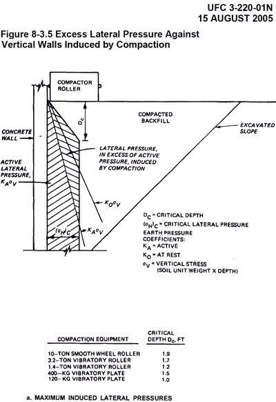
From page 8.47 of document
ufc_3_220_01n.pdf downloadable from
here we've got this diagram:
From the first graph, I see Z
c / h
c = K
A2
Now, here are my doubts:
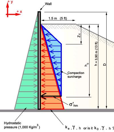
[COLOR=blue yellow]How can I guarantee that the
Hydrostatic pressure + the pressure from the sloping backfill + the compaction surcharge will always remain
< 0 ?[/color]
Additionally, will I use [COLOR=blue yellow]K
A[/color] or [COLOR=blue yellow]K
0[/color] ?
Throughout the thread we agreed to employ K
0 and now we have Ingold giving precedence to K
A over K
0. [COLOR=blue yellow]So, do I still stick with K
0 ?[/color]
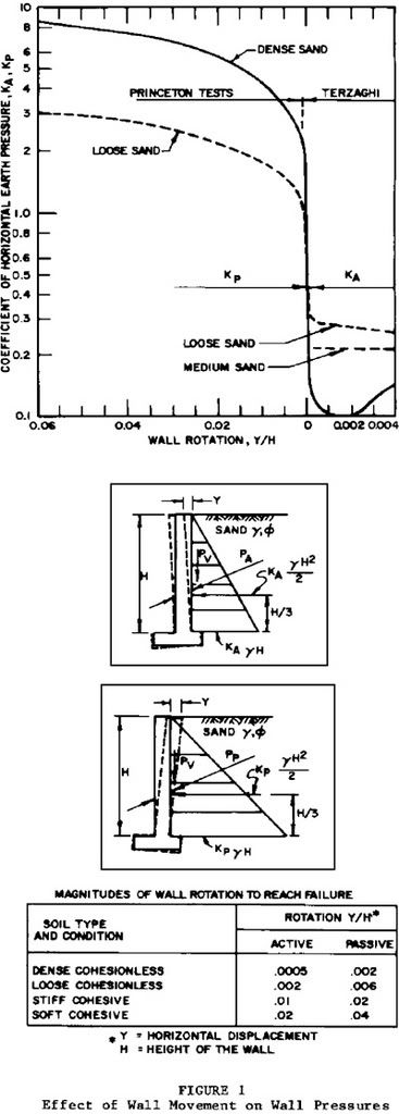
I understand that the difference between K
A and K
0 lies in how much rotation the wall can tolerate, right?. [COLOR=blue yellow]But, how am I supposed to know beforehand the value of the rotation ?[/color]
For example, the parameter needed to enter Figure 1 from NAVFAC 7.2 (page 7.2-60) is
the horizontal displacement Y.
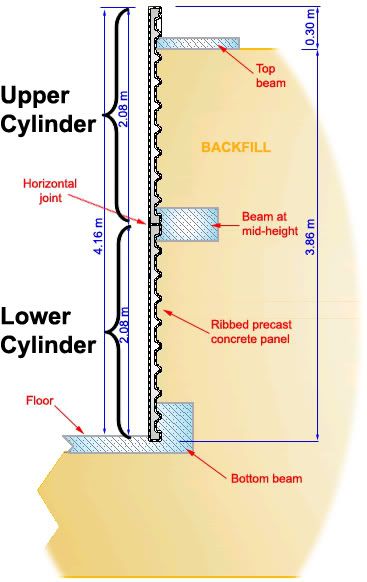
Remember from my previous post that the full height is achieved by stacking two cylinders:
Then, with the last picture in mind, [COLOR=blue yellow]
where do I measure the horizontal displacement 'Y' so that I can use it in Figure 1? Is it the largest 'Y' from span AB, for example ?
And why not use Rankine's formula instead of Figure 1?[/color]
(OK, Rankine's assumptions of a flat, frictionless wall are not satisfied here)
P
horiz. Active = P
vert. .
1
Tan
2(45º + [φ]/2)
In this case:
[φ] = 35º
[γ] = 1,900 Kg/m
3 = 119 pcf
Z = 3.86 m = 12.66 ft
Then, P
horiz. Active = 1,987 Kg/m
2 = 407 psf
So P
0 = 1.5 x 407 psf = [COLOR=white magenta]
610 psf[/color] [←] remember this
Re-calculating with an at-rest earth pressure of 50 pcf:
P
0 = 50 pcf x 12.66 ft = [COLOR=white magenta]
633 psf[/color] [≈] [COLOR=white magenta]
610 psf[/color]
[COLOR=blue yellow]So, what's the difference between Rankine's K
A and the K
A from Terzaghi's graph ?
What would be the value of Ingold's [σ]'
hm (or [σ]
HC for that matter) considering pneumatic rollers and rammers are employed for compaction?
And what about the value of D
c?[/color]
Lastly, all of this is from my intuition and thought. Maybe I am completely wrong and instead of having the backfill a pro-active role, the wall's behavior resembles a slab resting on an elastic foundation, and the soil has a mere re-active role, like I suggested in my previous post.
Or perhaps I should go for a Finite Element package. But, what use would the FEM be when I'm not fully understanding how the whole thing works in the first place?
And finally, given the risks involved, [COLOR=blue yellow]what would you do if you were in my shoes? Would you go ahead and apply this system in larger tanks (R > 15m, H > 3m) or would you stop here and stay under the pseudo-safe umbrella of tanks with R [≤] 15m, H [≤] 3m ?[/color] A sincere answer, based on experience, will be highly appreciated.
Thanks for reading !