Continue to Site

Eng-Tips is the largest engineering community on the Internet

Intelligent Work Forums for Engineering Professionals

  • Congratulations cowski on being selected by the Eng-Tips community for having the most helpful posts in the forums last week. Way to Go!

Simple Timber Frame Question

Status
Not open for further replies.

Everynameistaken

Structural
Jun 29, 2014
68
Hello,

I am working on a residential interior load bearing wall removal. We typically work on larger industrial projects so this is a little different for me!

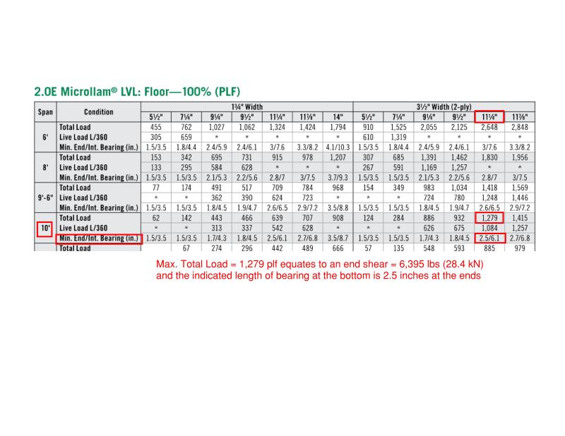
I have sized the LVL beam (3 1/2" x 11 1/4") for a trib width of 13' and span of just over 10', the beam shear/reaction load in almost 40 kN! So to support this I have a built-up post below the beam (jack studs?) of 4 - 2x4 nailed together.

The LVL beam will be hard up against the top plate which will remain and I am putting a 2x4 onto of the lvl to toe nail into the plate for lateral support along the beam length.

My question is at each end of the LVL beam I currently have one new king stud, this stud is nailed to the built up post and into the end grain of the LVL. DO i need more than one new king stud at each end of the beam??


Thanks
 
Replies continue below

Recommended for you

40 kN is about 9000 lbs. right?

Based on your info, I can't get an LVL to work with that kind of uniform load (based on Fb = 3,000 psi).

The LVL design will have a minimum bearing length on the bottom end that will be required based on perp. to wood bearing.
From my quick calculations, despite a unity of 1.3 for flexure, the indicated & required bearing length is 5.5 inches.

Here's a table with some numbers for an LVL similar to yours:
LVL_Table_icwv3x.jpg


Here's where this table comes from:


Check out Eng-Tips Forum's Policies here:
faq731-376
 
I have used a different supplier for LVL

See attached, the Mf I get is 28 knm (21,000 ft.lbs)

I pretty happy with the beam, its more the king stud requirment!
 
King stud quantity is usually dictated by out-of-plane loads, unless it happens to be the end of a shear wall. Since it is an interior wall your out-of-plane pressure is only 5 psf. So, one king stud should be sufficient unless the wall is a shear wall that needs double end studs or more, or unless the opening is to be filled by a roll-up door, etc.
 
everynameistaken said:
I have used a different supplier for LVL

See attached, the Mf I get is 28 knm (21,000 ft.lbs)

I pretty happy with the beam, its more the king stud requirment!
I am assuming you are designing using ASD. If so, I would not be happy with that beam. You will likely have serviceability issues.
Also, how are you getting 4 studs to hold 9k? I usually won't go over 2k/ stud for an 8 ft. stud.
 
Sorry - didn't realize you were using factored loads there.


Check out Eng-Tips Forum's Policies here:
faq731-376
 
I've contemplated this a fair bit in the past myself. Here's what I've got:

This is How We Do

1) Design the jack post group to act as a sufficient gravity column on its own without aid from the king stud group. As you're seeing here, the number of studs may well be governed by perpendicular to grain bearing issues anyhow.

2) Design the king stud group to deal with wind etc as mentioned by theonlynamenottaken.

This is what I see designers doing for the most part. Surely because it's simple and nobody can get their hands on enough fee to do much more even if they wanted to.

Other Things of Interest That We Leave to the Theoreticians

1) If one wanted to badly enough, one could consider the king studs to contribute to the axial capacity of the jack studs. No doubt, they do just that. But then you've got to give some consideration to the fasteners ability to transfer load from the jacks to the kings. As well, you end up with an eccentrically loaded post with moment etc. Lastly, depending on how fancy you wanted to get, you might also need to evaluate the combined stud pack as a stepped/tappered column for stability purposes.

2) Really, no matter what assignment we make in our calculations, the jacks and kings will work together to resist axial loads to some degree. And, thus, there will be moment in the plane of the wall. This raises an interesting question regarding the fasteners between the stud group and the sheathing as those fasteners will try to resist the lateral flexing of the stud group. Will the fasteners give out when this happens? They never seem to. For modest post loads, we typically assume that the sheathing fasteners brace studs in the weak axis direction. We don't, however, automatically assume that the fasteners can deal with an explicit lateral force from eccentric stud bending unless it's checked somehow. Fortunately, by the time that a stud pack takes serious loads, it's usually fabbed from enough plies that it hardly needs weak axis bracing.

3) The king studs could also use the jack studs to help with resisting wind load. But, again, you'd need to give consideration to the fasteners between the jacks and kings and the fact that the jacks only reinforce the kings for a portion of the the stud height. Folks do take advantage of this from time to time out of desperation. Questions about the appropriate wind load distribution through window frames come into play.

4) There is a joint where the top of the jacks meet the bottom of the header. Ostensibly, other than the influence of the sheathing, that joint is a pin which would represent a stability issue for header rollover. One of the important functions of the king studs is to rectify this. Does anybody check this numerically? Nope. And I'm confident that even a single stud is plenty for this purpose with some nails into the end of the header and/or the sill plate on top of the header.


I like to debate structural engineering theory -- a lot. If I challenge you on something, know that I'm doing so because I respect your opinion enough to either change it or adopt it.
 
Hi All,

Thanks again for the comments, alway good to get some discussion happening sharpens your own thoughts on the matter.

Yes, up north of the border always work in limit states design! But thanks for making sure someone didn't do something silly!!

I have designed the post exactly as KootK has noted, a stud pack that can take the load on its own, it works out to be 4 - 2x4 and then have a king stud running the full height to help laterally support the floor beam. Since we are interior and putting in an opening there is essentially no lateral internal wind / notional load on the king stud as the wall adjacent to the opening stays the same.

In a separate note, I completed my design of the LVL using hand calks and their tables, then as an independent check used their software, and saw something a little odd. The software calculated my bending moments and shears as much much less than what I had by the hand calks, same loading diagram exactly.
I looked a little closer and the software reduced the dead load by a "duration factor" by 0.65 since it is a permanent load. Then took this reduced DL into the load combination and factoid by 1.25. Now I do not agree with this at all. Timber has an ability to take higher loads for a chart time, under long sustained constant loading the timbers capacity is actually less not more. I believe the software has made a mistake with the "duration factor" as I always under stood Kd in O86 was a reduction factor for the beam capacity not on the loading?
 
I think your issue with the DL duration factor sounds correct and I'd immediately call the software company to discuss.

Check out Eng-Tips Forum's Policies here:
faq731-376
 
Status
Not open for further replies.

Part and Inventory Search

Sponsor