Continue to Site

Eng-Tips is the largest engineering community on the Internet

Intelligent Work Forums for Engineering Professionals

  • Congratulations KootK on being selected by the Eng-Tips community for having the most helpful posts in the forums last week. Way to Go!

Shaft can't fit in the hole.

Adam_JIN

Student
May 15, 2025
1
Hi everyone,

I’m new to this field, so please pardon me if this is a basic question.

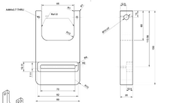
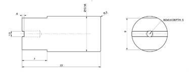
I recently submitted two designs—one with ⌀10 holes specified as H7, and another with a ⌀10 shaft specified as h6 (please see the attached drawings). From what I’ve learned, an H7/h6 combination should result in a clearance fit, but when I received the parts, the shaft wouldn't fit into the hole. The shaft length is only 22 mm. I’ve reached out to the manufacturers for clarification. It turns out the shaft and holes were made by two different companies, so I’m waiting to hear back from them.

In the meantime, I just wanted to confirm: is there anything in my design that might have caused this issue? Or is this more likely a manufacturing deviation?

Any advice would be greatly appreciated. Thank you!
 

Attachments

  • Screenshot 2025-05-15 at 3.12.14 PM.png
    Screenshot 2025-05-15 at 3.12.14 PM.png
    95.7 KB · Views: 35
  • Screenshot 2025-05-15 at 3.12.29 PM.png
    Screenshot 2025-05-15 at 3.12.29 PM.png
    169.9 KB · Views: 35
Replies continue below

Recommended for you

Hi everyone,

I’m new to this field, so please pardon me if this is a basic question.

I recently submitted two designs—one with ⌀10 holes specified as H7, and another with a ⌀10 shaft specified as h6 (please see the attached drawings). From what I’ve learned, an H7/h6 combination should result in a clearance fit, but when I received the parts, the shaft wouldn't fit into the hole. The shaft length is only 22 mm. I’ve reached out to the manufacturers for clarification. It turns out the shaft and holes were made by two different companies, so I’m waiting to hear back from them.

In the meantime, I just wanted to confirm: is there anything in my design that might have caused this issue? Or is this more likely a manufacturing deviation?

Any advice would be greatly appreciated. Thank you!
Have you measured the hole and compared them to your drawings?

More to the point, have your looked up the ISO tolerances in your Machinery's Handbook to find out what they actually are, and then compared them with your measurements?

Are your parts aluminium? Aluminium has a very high coefficient of friction, and it galls easily. Accurate aluminium parts must be anodized, or bad things happen.
 
Good point Dave, replace the set, it's same as a spiral bevel gear set due to back lash has to be a match set, can not be interchanged.
It is possible to interchange parts. Buy this way
It's guaranteed. Smile it's all good
It's not the same as a spiral bevel gear set - the gears are not match machined for most large production and the housings are not supplied by the gear maker. The only thing that is matched is with a shim set and I see no shims here. Any of a pair in a spiral set should be able to be replaced with any other of the same part/drawing and the only thing that happens is that, in the next assembly, a different shim is called for.
 
It's not the same as a spiral bevel gear set - the gears are not match machined for most large production and the housings are not supplied by the gear maker. The only thing that is matched is with a shim set and I see no shims here. Any of a pair in a spiral set should be able to be replaced with any other of the same part/drawing and the only thing that happens is that, in the next assembly, a different shim is called for.
I knew you would question this, lol, Each spiral bevel gear as it hobbed or ground with a special spiral cutting tool is verified with with a mating master at a set center distance. A pattern verification to make sure it us acceptable.
The master is the same as the mating part.
And are sold as a match set. Based on the exact
Center distance held . A set of shims are sold with the gear set. Because the center distance is inspected for the exact size on stamped on the the set. Then the correct set of shims are supplied. Then a assembly a pattern check and the exact backlash is recorded.
 
Yes the pinion is compared against a master gear and the gear is compared against a master pinion, but they are not match machined to each other.

Any randomly chosen pinion and gear can be set into a jig and shimmed; the shimming doesn't change the tooth face geometry of either gear. Either of them could be replaced, and a new center distance determined. They could be made at separate times in separate facilities. It is unlikely that gears will be so made, but in this case the cylindrical part could be pumped out on a screw machine and the other produced on a CNC by separate companies.

All that is happening by stamping them as a pair with a dimension is to decrease the effort the end user might make; using them would still be possible if they were not so marked, just more effort. In this case the parts should be usable without matching them and it is likely that, like the gears, they won't be match machined in order to function.

(edit mistyped; italicized)
 
Last edited:
This is a distraction as the original problem. The thread isn't high precision gears and blacksmithing isn't a typical production process.
 

Part and Inventory Search

Sponsor