Continue to Site

Eng-Tips is the largest engineering community on the Internet

Intelligent Work Forums for Engineering Professionals

  • Congratulations KootK on being selected by the Eng-Tips community for having the most helpful posts in the forums last week. Way to Go!

Shaft can't fit in the hole.

Adam_JIN

Student
May 15, 2025
1
Hi everyone,

I’m new to this field, so please pardon me if this is a basic question.

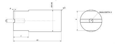
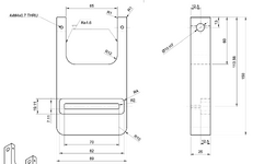
I recently submitted two designs—one with ⌀10 holes specified as H7, and another with a ⌀10 shaft specified as h6 (please see the attached drawings). From what I’ve learned, an H7/h6 combination should result in a clearance fit, but when I received the parts, the shaft wouldn't fit into the hole. The shaft length is only 22 mm. I’ve reached out to the manufacturers for clarification. It turns out the shaft and holes were made by two different companies, so I’m waiting to hear back from them.

In the meantime, I just wanted to confirm: is there anything in my design that might have caused this issue? Or is this more likely a manufacturing deviation?

Any advice would be greatly appreciated. Thank you!
 

Attachments

  • Screenshot 2025-05-15 at 3.12.14 PM.png
    Screenshot 2025-05-15 at 3.12.14 PM.png
    95.7 KB · Views: 34
  • Screenshot 2025-05-15 at 3.12.29 PM.png
    Screenshot 2025-05-15 at 3.12.29 PM.png
    169.9 KB · Views: 34
Replies continue below

Recommended for you

The drawing does not appear to be explicit in telling how the holes on opposite sides line up with each other. Many makers would use a single operation to make those holes, but not all manufacturers will - they might just flip the part over and not notice any differences. It is slightly possible the shaft is not straight.
 
What were the actual sizes of received parts? H7/h6 could have been a size-on-size fit, which I would not expect to go. If the saddle was machined after the 10mm hole was bored, there may have been some residual stresses relieved and the hole went out of round - what material was used? Are you located in USA - did the parts suppliers understand what the tolerances meant?
 
OP
the part with the two coaxial holes is lacking true positioning. one hole should be a datum.
the other hole should have FCF true position .
there is nothing that tells the manufacture.
holes are coaxial within .001 inch.
holes will be the correct diameter. but not coaxial. the shaft must be fcf with .001 inch
straightness.
in manufacturing the shaft would require to
be cylindrical ground centerless method.
the both holes would require to be machined in line.
in theory the end of the shaft should fit.
in actually will not due to straightness, roundness, and addition no burrs permitted.
 
Guys, it's at 22 mm long shaft. It's not possible for it to simultaneously be in two holes separated by a 65 mm gap.
 
Ah, yes. None of this makes sense, particularly the tying to "two different companies" as a possible cause.

It will by funny to find that the shaft was turned to size and then someone grabbed it and chewed up the surface doing some other operation and the assemblers are just lying about it not fitting when they should have rejected the part.
 
H7/h6 is an ISO standard, ISO 286. The minimum gap is 0.00 mm, so it's possible that the shaft has some thermal expansion relative to the hole and that is causing the problem, but the chances of making parts like that is small. Still, this is one of those 20-questions posts.

The OP claims to have the parts in their hands and could, potentially, measure their diameters, but apparently has not. Also could have a photo of the parts. It's what makes this such an interesting game.
 
Last edited:
That's the fun thing. It would be entirely useless if there was the casual acceptance of shafts bent into eye-bolt shapes and wandering holes, wouldn't it? However did anything ever get made before (E) was invented? Even if that was the case, the shaft would still fit at least some distance into the hole before the potential banana shaped shaft (for example) stopped going in.

So, sure, according to some standard, it would be acceptable to make a 10 mm diameter, 22 mm long shaft into a corkscrew.

Is that the most likely problem?

I don't know what is "most likely" the problem. But you seem to ASSUME that is not. (that the envelope is NOT the issue)

ANSI has its own standards regarding the limits and fits. ANSI/ASME B4.1-1967 and ANSI B4.2-1978 so another assumption on your part.
(Those two "old" standards will be converted shortly into ASME Y14.39 Limits and Fits). But anyway, I prefer to not assume anything and ask questions for further clarification.
 
If the Ø10 mm shaft was centerless ground it could easily have a three lobed profile that checking with a micrometer can't detect.

"However did anything ever get made before (E) was invented?"
ASME's Y14.5 Rule 1 is the default. "Envelope Rule" or "perfect form at MMC
It might have appeared as early as 1953 in military standard MIL-STD-8A .

I agree with that.
I have two questions however:
If ISO 286 is the default standard (and if E is not intentionally invoked on the drawing) does the ISO 286 has the envelope by default enforced (just by mentioning the ISO 286 standard)?

If B4.1 and B4.2 (and not ASME Y14.5) are used then IS the Rule#1 enforced just because B4.1 and B4.2 are invoked?
How do we know the perfect form at MMC is used?
 
Last edited:
The envelope rule does not apply to ISO.

While a micrometer cannot easily detect three-lobed profile, simply rolling the item on a reasonably flat surface will, no quantitative measure required. Even with a micrometer, rotating the part will show that the opposing part of the lobe does not remain on the centerline of the part, but goes off-center as the part is rotated; possibly less easy to spot than that the rolling of the item is irregular and favors only 3 orientations.
 
Gentlemen verifying the shaft for roundness straightness, and size is simple. , it's done often for gage pins. Simple to grind and simple to verify. Instruments that are ultra precision are use , calibrated to standard gage blocks.
Or CMM.

Now the trick or tip is the component with two coaxial holes has to be trued up by super precision cnc surface grinder. For tooling purposes.
Then held in a 4 or 5 axis ultra precision rotab.
With a ultra precision vise. The holes will require
Jig bored or jig ground to be precise.
The parts should have been contracted as a match set. To the same contractor.
The holes held at high limit. The shaft held to the low limit. This can be easily held with centerless grinding. If there is allowable centers on each end it would be even can be held with standard ultra precision cnc od grinder.
 
If they are contracted as a matched set, what happens 5 years from now when one of the shafts is lost and a new one is required?

Is it back to the blacksmith era where all the parts are brought in and are hand-fit without any measurement needing be made?

I've been down the "matched set" road and it becomes a tremendous hassle when interchangeability is required.
Good point Dave, replace the set, it's same as a spiral bevel gear set due to back lash has to be a match set, can not be interchanged.
It is possible to interchange parts. Buy this way
It's guaranteed. Smile it's all good
 
important tip here is now the supplier now understands the importance of what the assembly requires. and the lack of communication to the suppliers of the design intent. while most likely it will be interchangeable. I seen it all the time stupid stuff on drawings and I would see machinist scratching their heads. they would say what in the world. I say make to the drawing regardless what you think.. there's forces and stress values that you don't know.
the key is communication to the poor guy on the floor.
 

Part and Inventory Search

Sponsor