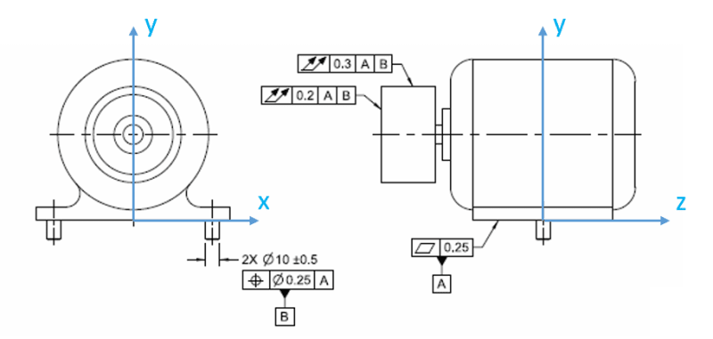
JP/pmarc,
So I've given this some thought because the portion in 12.6.8 stating "the datum features do not establish the location of the axis of rotation, but they do constrain the orientation of the axis" really threw me through a loop. It took me a bit to suss out exactly what is meant as I think there is some nuance there between "established" and "constraint" as the datum features in 12-16 |A|B| certainly are able to constrain all translational/rotational DOF of the axis of rotation and the datum references are not modified (datum translation/customized DRF). I think perhaps this wording is misleading or at least confusing to me and would be better phrased "the datum features do not establish the location of the
runout tolerance zone, but they do constrain the orientation of the
runout tolerance zone" - my reasoning is as follows.
The conclusion I have come to is that in keeping with the standard's definition of runout, the scheme shown in Y14.5-2018 fig 12-16 is still closely tied to the specific use and behavior of a dial indicator during measurement. Assuming the conventions below and considering the runout tolerance on the diameter, it seems the scheme is meant to replicate fixing a dial indicator base in orientation (u,v,w) WRT to |A|B| and measuring runout of the surface of interest by traversing along (z) while rotating the feature about the axis of rotation. In this way, pure (x,y) location error of the axis of rotation does not show up on the indicator however (u,v) orientation error of the axis of rotation will. The fact that the measurement occurs fixed to a frame other than the axis of rotation while the feature is rotated about the designated axis of rotation is what creates this phenomenon.
Taking this a step further, I tried to envision how this could be replicated by a dynamic profile tolerance as dynamic profile to |A|B| would produce a different result as the location of the tolerance zone would be fixed in location/orientation fully to |A|B|. If the feature(s) which define the axis of rotation (for example the ID's of two bearings) is denoted datum feature C my first guess would be a specified 0.3 dynamic profile tolerance wrt |A(u,w)|B(v)|C(x,y)| however this wouldn't account for variations between the shaft/bearings so perhaps a note that the feature must be measured while rotating about the designated axis of rotation - the FCF could potentially be changed to show |A(u,w)|B(v)| in that case.
Thoughts?

