Continue to Site

Eng-Tips is the largest engineering community on the Internet

Intelligent Work Forums for Engineering Professionals

  • Congratulations The Obturator on being selected by the Eng-Tips community for having the most helpful posts in the forums last week. Way to Go!

Revisit of Wood Portal Frames

Status
Not open for further replies.

medeek

Structural
Mar 16, 2013
1,104
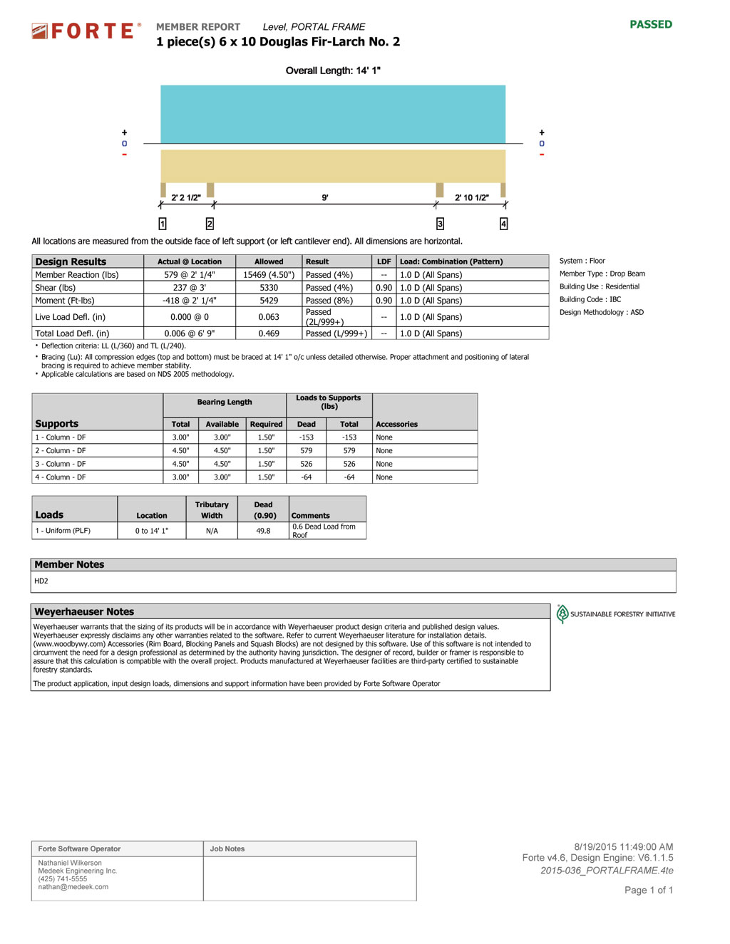
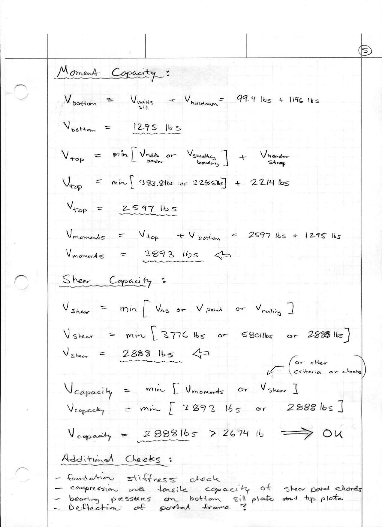
My previous analysis or attempts thereof of a typical wood portal frame assumes that the holdowns at the foundation and the moment connection of the nail grid into the header (and strap) more or less share the moment load equally and I basically give it a pass provided the combined capacity exceeds the actual load. See page 5 of previous analysis below:

PF5.jpg


However, is this assumption correct? or perhaps close enough?

My most recent spreadsheet for portal frames so far does not take into account the moment capacity of the nail gird, straps and sheathing. It essentially treats the pony wall and shear panels on each side of the opening as separate (segmented) shear walls, see below:

2015-036_PFH1.jpg


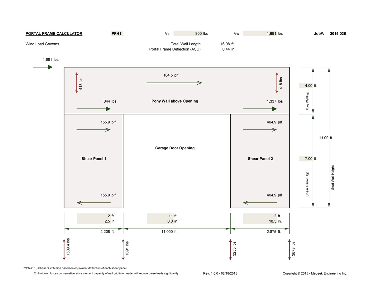
When the two legs of the double portal frame are different lengths I utilize the three term deflection equation from the SDPWS to compute the shear force to each leg such that the deflections are equal.

The problem I see with my current attempt at an analysis is that the holdown forces will actually be significantly less than shown since the moment connection at the shear panel/header interface (nail grid and strap) will decreases these forces at the foundation. The question is how do I quantify this decrease in holdown forces without an elaborate FEA model. I'm wondering if anyone has done this sort of thing before and might have some hints or ideas.

The other thought that came to me is the moment connection at the top of the shear panels will make the entire portal frame stiffer and hence decrease deflection as well as make it attract more load in a rigid diaphragm analysis.

A copy of my spreadsheet is located here is anyone is interested in looking at my algorithm for computing the deflection and the distribution of shear.


I actually started with the 4 term deflection equation but I could not get it to give reasonable answers when the difference between the two legs was only slightly different. I think it may have something to do with the non-linearity of the equation and the nail slip term.


A confused student is a good student.
Nathaniel P. Wilkerson, PE
 
Replies continue below

Recommended for you

Malone's book has quite an in depth discussion about this sharing of moments and how it is dependent on the relative stiffness of the framing versus the foundation. Obviously little or no holdown capacity (fixture at the base) or a weak or flexible foundation will drive the moments to the joint at the top of the shear panels, see Figure 13.7 page 471 of his text. If the header/pony wall section is less rigid than the shear panels (piers) then it will flex and the panels will act like segmented shear walls, see discussion in Section 13.4 and Figure 13.13 on page 479.

My thinking is that a relative stiffness can be determined by calculating the moment of inertia of the pony wall/header and the piers as per example problem 14.6 in Malone's book and then converting this to an equivalent rectangular section that can be dumped into a matrix analysis. Unfortunately, this may be a bit too complex for my Excel spreadsheet and may need to be programmed in Perl.

The other thing to note is that my current analysis neglects the counteracting weight of the dead loads (load case 7: 0.6D + 0.6W) that will offset the tension on the holdowns, however I am fine with this conservative simplification for now.

A confused student is a good student.
Nathaniel P. Wilkerson, PE
 
The particular portal frame I'm looking at right now is located at the gable end of a garage so the dead loads are relatively minor. However, just for curiosity I input the portal frame header into Forte to look at the reactions:

PFH1_60DEADLOADS.jpg


It is interesting to note that at the outside studs the beam will deflect upwards and the dead load will actually increase the tension force in the holdowns at these locations. In reality the header is attached to the sheathing by some ridiculous nailing (3" o/c) so this uplift at the ends will probably be distributed into the shear panels and not all concentrated at the outside studs.

If my portal frames were not so atypical I would simply use the numbers in the APA TT-100 document to validate their use.

A confused student is a good student.
Nathaniel P. Wilkerson, PE
 
I'm also beginning to wonder if strapping at the corner of opening between the header and the shear panels would not provide the same sort of moment capacity as a portal frame yet still have the vertical continuity of the studs going from sill plate to top plate, similar to the FTAO method. This could be an advantage where the pony wall above the header becomes too tall and creates a significant hinging problem, one of the downsides of this method.

A confused student is a good student.
Nathaniel P. Wilkerson, PE
 
I guess what is bugging me with my use of portal frames in my design and engineering analysis is the ability to actually do any real engineering with these modes of construction. The actual design (draft) I've shown below:

PFH_EXAMPLE2.jpg


This particular case was a bit more challenging than my typical garage walls. The wind loads gave me a total shear load of approx. 4800 lbs. The two available wall spaces on each side of the door are too narrow for conventional shear walls segmented or perforated (aspect ratio of 3.8 or greater) so the only available segment is the 4'-3.5" section on the right of the man door. I also considered using FTAO around the door openings but I've never been very comfortable with that method where it involves doors instead of windows, partly due to Section 13.4 of R. Terry Malone's book, perhaps I am misguided in this respect.

If I use only the 4'-3.5" segment my holdown forces (12,320 lbs) and unit shear in this panel become too high in my opinion, so I wanted to try and pick up some of that shear in the rest of the wall, hence the portal frame.

Based on my analysis with Woodworks Software and distribution of shear based on deflection I get 1618 lbs picked up by the portal frame and 3142 lbs picked up by the shear wall (SWL B-1), with this load distribution my uplift forces at the shear wall are a more manageable 8,000 lbs and the unit shear is considerably reduced as well.

I am not sure if there is any problem combining the two methods in one wall line but as long as they are deflection compatible I don't see a problem.

My one other concern with this particular configuration is the pony wall height. The prescriptive code (IRC & IBC) don't seem to have any direction on max. pony wall height. However other local codes have adopted a 4' max. on this height:


A confused student is a good student.
Nathaniel P. Wilkerson, PE
 
Now there is a bit more substance to the portal frame calculator. I'm using Zeno Martin's paper as a guide and using a mechanics based approach as recommended by Terry Malone. The shear distribution between the shear panels is based on equal deflections.

The moment distribution between top and bottom of the shear panels is based on capacity, this seemed the simplest and most reasonable way to approach this and it also agrees with Martin's paper.

Give it a go and let me know what you think:


A confused student is a good student.
Nathaniel P. Wilkerson, PE
 
I thought I should mention that I wrote Terry Malone an email a few days ago inquiring about this treatment of portal frames within his text. A couple days later he wrote me back and offered some very helpful advice and suggested I use the mechanics based approach as outlined in Zeno Martin's paper.

A confused student is a good student.
Nathaniel P. Wilkerson, PE
 
In his text he uses a lot of FEA or matrix analysis to generate moment diagrams for the members or analogs, however he suggested that with the mechanics approach Martin's model accurately predicted the strength to within about 5%. Hence, the added effort to generate more accurate finite element models are probably a waste of time.

As I mentioned in a previous thread some additional checks might also be:

1.) Foundation stiffness check for stemwall foundations, thickened edge slab foundations (slab-on-grade) and the stemwall foundation with thickened edge slab at doorways as shown above.
2.) Compression and tension check of shear panel chords (secondary strap on outside of portal frame really needed?).
3.) Bearing pressure check where chords contact sill plate and possibly top plate or header.
4.) Bending check of the header combining 0.6D and the wind or seismic load imparted to the header via the tension straps.

My current method of calculating the deflection of the portal frame uses the three term SDPWS shearwall deflection equation which deals with nail slip, shear, holdowns and bending of the shear panels. This deflection is then combined with the deflection of the pony wall (bending, shear and nail slip only) to arrive at the total deflection of the portal frame. The deflection equations are making the assumption that the shear panels are behaving as typical segmented shear walls so this may not be completely accurate and is probably over estimating the deflection.

I am left wondering if anyone has done any research into the deflection of portal frames and if there is any development of the math to predict this deflection?


A confused student is a good student.
Nathaniel P. Wilkerson, PE
 
My suspicion is that the math will never accurate predict real world construction tolerances so it will end up being very un-conservative.
The frames are likely flexible enough that the majority of the load is going to go elsewhere to stiffer elements.
 
Status
Not open for further replies.

Part and Inventory Search

Sponsor