Tek-Tips is the largest IT community on the Internet today!

Members share and learn making Tek-Tips Forums the best source of peer-reviewed technical information on the Internet!

  • Congratulations MintJulep on being selected by the Eng-Tips community for having the most helpful posts in the forums last week. Way to Go!

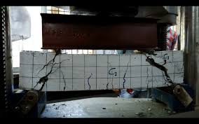
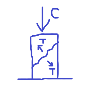
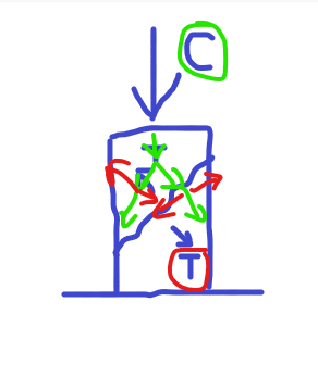
RC Wall Under Strength for Shear

Status
Not open for further replies.

Ericson66

Structural
Joined
Apr 7, 2016
Messages
12
Location
AU
What are economic engineering remedies for strengthening 1m thick wall for shear under soil loading.

Thanks in Advance
 
Rod,

There are several methods to calculate Ko, I happened to like the simple method, Ko = 1-sin∅. For granular backfill, the usual internal friction angle ranges from 27° to 33°, and the range of the resulting Ko is 0.45 - 0.55. I've spent a lot of time on hydroelectric project, in which 0.5 was the norm for the preliminary design. Please note that Ko can go much higher should compaction is to be considered. (Usual range of Ko, loose sand 0.4, dense sand 0.6, with tamping 0.8)
 
retired - where did you get that the fill was granular? As the sketch indicated the Ko came form a geotech report, I'd be inclined to stick with the value they provided.
 
retired13's last response got me thinking...Ericson66, have you considered using reinforced backfill (mechanically stabilized earth) to reduce the soil pressure on the wall?


Rod Smith, P.E., The artist formerly known as HotRod10
 
I agree with phamENG. I would make very sure that you analyzed this appropriately before you make a claim that it is deficient. What does your code allow in terms of decreasing the angle of inclination of diagonal compressive stresses and increasing the factor controlling the ability of diagonally cracked concrete to transmit tension and shear? Traditionally, these may be taken as 45 degrees and 2.0 but perhaps can be optimized if there is low steel strain.

I was thinking you could drill holes through the wall and pressure inject a chemical grout into the surrounding soil but this typically requires cohesionless soil with little to no fines. It would be nice if some of the geotechs could offer their opinion on this matter.

 
Gentlemen,

If you are comfortable with the Ko value in the sketch, then ratio out the resulting shear force by Vrevised = V*(0.37/0.5), note this is non-factored force.

 
I think BridgeSmth might be on to something.
OP states only 5m of wall has been built.
MSE or grout injection might be possible.
That might "solve" the problem but it doesn't answer the question of how to improve shear capacity. For that, I assume shear friction would be helpful approach.
 
I'm liking Bridgesmith's thinking. Could you drill holes and do soil nails, or other tie-backs to lessen the load?
 
We have used FRP (Fiber Reinforced Polymer) for reinforcing existing concrete walls and slabs, I suggest looking into it.
 
Darn those metric dimensions! I was envisioning 5ft, not 5m, built, and assuming that it had not yet been backfilled. If it has, then some sort of soil-mixing or grout injection might be preferable to re-excavating to put in geogrid.

Rod Smith, P.E., The artist formerly known as HotRod10
 
Erikson66 said:
Any one with experience with this product as a solution to shear problem Shear design of externally bonded FRP systems??


Not sure how you would do this on a flat wall. This is intended for beams where you can wrap it completely around, or at least on 3 sides. If you were thinking of that route, I would rather drill and epoxy U bar stirrups into the wall. However, I think there have been much better suggestions thrown out there so far.
 
It it hasn't been backfilled yet, why don't you backfill it (or a portion of it) with CLSM?

Correct me if I'm wrong but I'm guessing the whole thing is cofferdammed outside of the perimeter of the raft slab. Which only leaves about 4.5ft of width to backfill. MSE wouldn't be very effective in such a thin strip.
 
Correct me if i'm wrong but I thought FRP would only help you with in-plane shear in a wall. I didn't think it could do anything for out of plane shear forces?
 
@JoelTXCive - Thank you for the clarification, you are correct, I overlooked the part about shear and was thinking about the bending in the wall.
 
Whats the contibution of compression (2.5MPa) to shear capacity through a section of wall ?
 
For a rudimentary physical description:

Diagonal shear - the compression will effectively "close" the cracking caused by shear and thereby increase the shear capacity.
Shear Friction - the compression will add to the normal force, increasing the friction occurring on the subject plane and increasing the shear capacity.

How these physical phenomenon are applied to design depends on the code you're using. I think you're in Australia - I'm afraid I'm not familiar with your specific design code requirements so some other folks will have to help you with that.
 
Shear phenomenon is caused by compression. Remember in concrete lab to verify the shear plane by compress the cylinder to fail!?
 
retired - we used a beam with (roughly) constant moment to test shear. Compressing a cylinder on the side tests for a transformed tensile failure.

shearconcrete_bzrjkq.jpg
 
I think this is the usual way in concrete lab to determine compressive strength of the supplied concrete.

s_ewac4k.png
 
Retired,

That type of break is not the ideal break in compression tests. A proper test results in stresses something like this. Mohr's circle and all
image_huggk1.png
 
The shear crack will propagate then leads to crumbling of the specimen. The point here is compression causes shear to occur, or depress shear force. I would agree that the compressive tends to close a gap AFTER a gap is formed, similar to the effect of post-tensioning.
 
Status
Not open for further replies.

Part and Inventory Search

Sponsor

Back
Top