Please refer to the snips below and the attached PDF of the same.
I also wanted to explore a bit more the business of L-retraints (lateral only / one flange) being taken as equivalent to F-restraints (lateral restraint + cross section rotational restraint). A brief summary:
1) A while back, Steveh49 dropped on us the extinction level bombshell that AS4100 considers L-restraints equivalent to F-restraints in many cases. I don't think that I was alone in finding that shocking.
2) I came to a revelation of my own that, in fact, both AISC and AS4100
routinely assume that rotational restraint exists where only an L-brace is present. The ubiquitous case of that being simple span beams with intermediate, lateral braces on the top flange. So assuming rotational bracing at locations only having lateral bracing isn't an outlier thing, it's an all the time, everywhere thing. And it needs to be explained in that context.
3) In a post dated [27 Nov 19 01:59], tomfh and I explored how this applied to simple span beams and came to the conclusion that, indeed, it was appropriate to consider L-braces as F-braces for such cases.
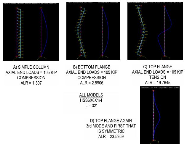
Where I'm at now is that, if L-bracing is going to be effectively taken as F-bracing in some situations but not others, then I'd like to know the rules of the road. When is it okay and when is it not? To that end, I've studied the cases below. This is our usual W27x84 with the center point load. I've placed F-bracing at the inflection points and L-bracing in between. From the perspective of both AS4100 and AISC, the span between the IP F-bracings would be treated as an independent design segment within which the L-bracees could be assumed to prevent cross section rotation. So the point of the exercise, then, has been to assess the truthiness of that claim.
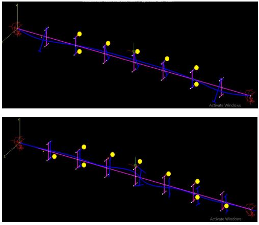
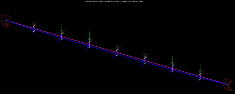
CASE 1
Here, at an ALR = 8.3991 and no bracing at the 1/4 points, it would appear that the L-braces are
not effective rotational restraints. That said:
a) It appears to me that it is the buckling of the the spans to the left and right of the IP F-braces that is encouraging the bottom flange "kick out" between the IP F-braces.
b) To an extent I think that one can say that, if a buckling mode that would induce rotation at the L-braces occurs at a wildly high ALR, that's not really a repudiation of the notion that such L-braces are effectively F-braces.
CASE 2
At an ALR = 24.1222, this is the same as case one but with the addition of bottom flange bracing at the 1/8 th points. As can be seen by the snaking buckled shape between IP L-braces, and the relative absence of cross sectional rotation within that segment, this removes the tendency for twist between the IP F-braces entirely and restores that segment to a state where the assumption that the L-braces are effective F-braces would be appropriate. So a nice benefit of case two is that the end segments no longer buckle and encourage section rotation between IP F-braces. I would argue, however, that this benefit could be gained in two ways:
a) Provide actual bottom flange L-braces at the 1/8 th points as shown or;
b) Simply design the the segments left and right of the IP F-braces such that they don't buckle without the 1/8 th point bracing.
I feel that this is an important equivalency.
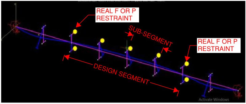
The Proposed Rules of the Road for L-braces Equivalent to F-braces
Speaking the parlance of AS4100, and being mindful of the AS4100 distinction between "segment" and "sub-segment", I tentatively propose that intermediate L-braces may be assumed to be equivalent to F-braces within a design segment, and therefore taken as forming sub-segments, when:
1) The design segment being studied is itself bounded on each end by F-braces (real, physical ones).
2) The design segments either side of the segment being studied, if present, have been properly designed to preclude buckling there.
3) A "compression flange" shall be defined as any flange experiencing compression anywhere within the design segment being studied, regardless of whether or not that flange would experience compression at the particular location of any given L-brace.
4) Any design segment may have as many as
two compression flanges, as dictated by loading conditions. In such cases,
both flanges must be independently stabilized laterally and independently evaluated for stability.