Continue to Site

Eng-Tips is the largest engineering community on the Internet

Intelligent Work Forums for Engineering Professionals

  • Congratulations cowski on being selected by the Eng-Tips community for having the most helpful posts in the forums last week. Way to Go!

position tolerance

Status
Not open for further replies.

dho

Mechanical
May 19, 2006
255
can a feature's position tolerance having itself as a datum?
i like to control the hole location real tight ref to main axis and end plane, but it could be loose relative to flange orientation.
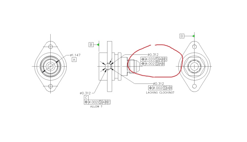
if the part axis A, end surface B, the hole in concern C, the position tol of the hole "POS dia .002 S A B C".
or i must generate the line connecting two flange holes as D, then specify "POS dia .002 S A B D"?
thanks.
pos_tol_ejj9uz.jpg
 
Replies continue below

Recommended for you

See 7-41 from 2009. Use same concept, but add flange/holes location to the same DRF.
 
so, my 3/31/16, 19:46 thread, geo tol in red "circle" would be acceptable.
thanks.
pos-tol_ly9fox.jpg
 
Drop D as tertiary from upper segment.
Drop the second segment
Add 2x pos. req. for the flange holes to A primary and B secondary.
Add profile req. for the flange shape/size to A primary and B secondary.
 
dho,

When we ask about part function, what we mean is how does this part interface with the rest of it's related components. I see a flange with holes in it. This highly suggests that the flange bolts against something. If this is true then the flange face would probably serve as a better---and more functional--primary datum feature.

I just can't help but bring back up your notion that proper GD&T has nothing to do with function. It has everything to do with function, that's why we're asking questions before just throwing out random suggestions. This part can be properly toleranced in a variety of different ways but the one that communicates function is the one to use.


John Acosta, GDTP Senior Level
Manufacturing Engineering Tech
 
i know NOT much in geo tol. but i think geo tol is a tool to explain the designer's requirement in a universal way so everyone interpret it the same.
so, in this thread, the question is how to geo tol the part so the .312 hole is intersect the main bore in 90 degrees (most important), and at a specified distance from front end surface A, (second important). and lastly, line up with the flange. (it is well asked in my initial posting.)
just as ASME Y14.5 (2009) fig 7.41, it tells the proper way to geo tol, a redial hole WITHOUT discussion how this part is designed if proper for its function.
i know NOT much geo tol, i say it again. so, i am looking for help/guidance.
thanks to everyone who answered my call.
 
dho,

This is futile. You acknowledge that you don't know GD&T yet you argue that it isn't necessary to know part function in order to properly implement it.

Good luck getting anyone else to help. You've argued your way out of any real help thus far.

John Acosta, GDTP Senior Level
Manufacturing Engineering Tech
 
i would allow different opinions. i would categorize this as discussion. if it is some sort argument, what is wrong to argue about a tech issue?
the end of this thread.
 
The problem is that you're arguing about something that you admittedly know nothing about.
Now you can end the thread.

John Acosta, GDTP Senior Level
Manufacturing Engineering Tech
 
Status
Not open for further replies.

Part and Inventory Search

Sponsor