Is it acceptable to apply a position tolerance to a basic feature?
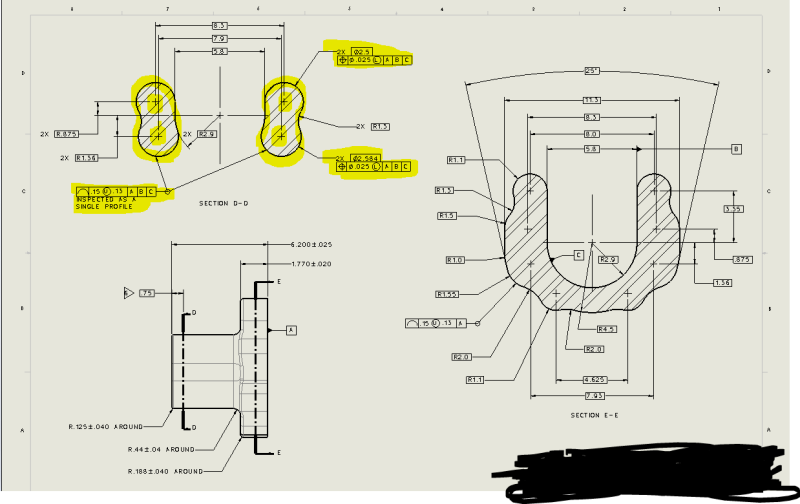
The form (and orientation) is already controlled by the profile tolerance, however I need to hold tighter control on certain parts of a the profile as they approach LMC.
Something like the image below, using position of the diametric features in addition to the profile of the whole.
Thanks!
Bear with me an my hand-mouse markup.... the red boundary represents MMB of the profile, the red-dashed circle represents smallest diameter that fits within the profile boundary at worst-case position, the red cross represents the center of that red-dashed circle. Now, what I'd like, is to further restrict the center of that circle, so that it must fall within the blue-dashed circle, while simultaneously the form must fall within the profile min/max boundaries.
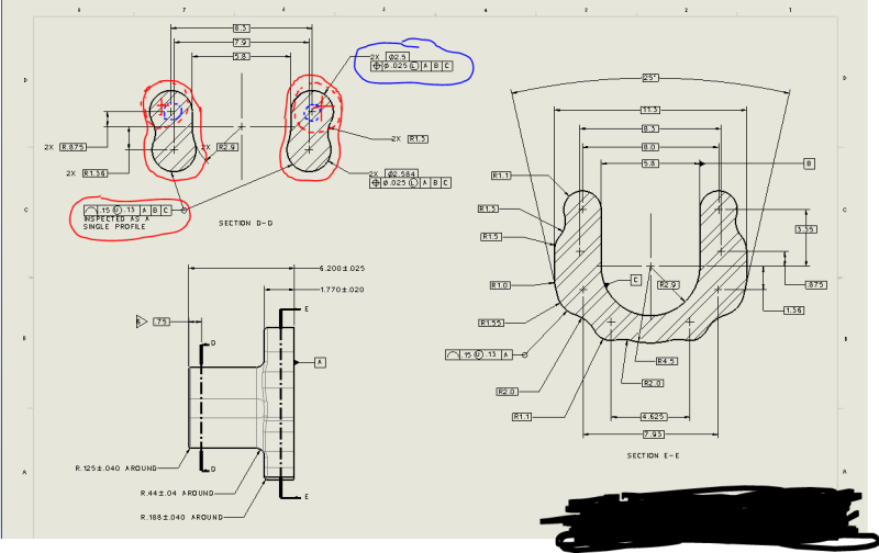
Hopefully that makes sense!")
The form (and orientation) is already controlled by the profile tolerance, however I need to hold tighter control on certain parts of a the profile as they approach LMC.
Something like the image below, using position of the diametric features in addition to the profile of the whole.
Thanks!
Bear with me an my hand-mouse markup.... the red boundary represents MMB of the profile, the red-dashed circle represents smallest diameter that fits within the profile boundary at worst-case position, the red cross represents the center of that red-dashed circle. Now, what I'd like, is to further restrict the center of that circle, so that it must fall within the blue-dashed circle, while simultaneously the form must fall within the profile min/max boundaries.
Hopefully that makes sense!