Continue to Site

Eng-Tips is the largest engineering community on the Internet

Intelligent Work Forums for Engineering Professionals

  • Congratulations waross on being selected by the Eng-Tips community for having the most helpful posts in the forums last week. Way to Go!

Poll Question: % UDL 1

Status
Not open for further replies.

FoxSE14

Structural
Feb 5, 2011
131
Audience Task: Provide 60% UDL value for a wide flange steel beam, given the following parameters....

Code: AISC, Table 3-6 (provided below), Use LRFD capacities.
Beam Size: W16x31.
Beam Length: 20 Feet.

....What value do you get? Please share.


IMG_3398_zf6bx2.jpg
 
Replies continue below

Recommended for you

0.6*81=48.6 kips. If it were me, I'd round up to 50.

Why does this seem like a trick question?
 
Can you explain what this is all about?

 
Thanks, jayrod.

JAE: Sure will, looking for a sampling of answers first though.
 
Provide 60% UDL value

I think the key/trick is the "UDL", then ask you to use the table of "TUL" table. Is the design dead load = 800.6*TUL?
 
Agree with Jayrod.

Someone is designing some connections and is annoyed by an EOR.
 
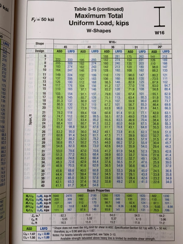
I also obtained 48.6 kips. Others in our office also obtained 48.6 kips.

Brad - close, I am designing some connections and annoyed, not with EOR, but with our fabricator client. On the first pass, their new detailer has taken it upon themselves to program his detailing software to make a generic first pass based on 0.6*TUL/2 i.e.: the capacities of the connections he has designed are sometimes as low as 48.6/2 = 24.3 kips. Obviously a problem, as I assume the EOR (who will ultimately approve our connection designs) is looking for the capacity to be 48.6k, at a minimum.

The fabricator we work for is accusing us of over-designing. We are about to accuse the detailer of unsafe design. Just looking for consensus.


(yes, yes, actual reactions at each connection is preferred...already barked up that tree. We've worked with this client before, the detailer change seems to be the catalyst here.)
 
As someone not familiar with US codes, who rarely does building design and does steel design even less, it looks like a pretty straightforward table lookup and multiply by 0.6 = 48.6 kips.

Doug Jenkins
Interactive Design Services
 
I think the language shall be modified to " Provide 60% UDL value, at each end, for a wide flange steel beam. Or, " Provide 60% UDL value for a wide flange steel beam at each end.
 
retired13 said:
I think the language shall be modified to " Provide 60% UDL value, at each end, for a wide flange steel beam. Or, " Provide 60% UDL value for a wide flange steel beam at each end.

I think the EoR should - at a minimum - place the connection reaction on the drawing via table etc., OR, better still - like the rest of the world (outside North America) - design the f..ing connection. RANT OVER!
 
retired13 said:
I think the language shall be modified to " Provide 60% UDL value, at each end, for a wide flange steel beam. Or, " Provide 60% UDL value for a wide flange steel beam at each end.

That's another question, and as stated could be taken to be ambiguous.

The OP asks for 60% of the total LRFD UDL for a specified beam 20 ft long, which appears to be straightforward.

Doug Jenkins
Interactive Design Services
 
Well, here's an interesting development. The help file for a known piece of connection software actually gives the following (which aligns with detailer's approach):

"The UDL % is a way to have the link calculate the design shear forces on a beam in your model. This is done considering the AISC 14th edition manual Tables 3-6, 3-7, 3-8 and 3-9 for wide flanges and channels. These tables have a Wc/Ωb for ASD and a φWc for LRFD and units of kip-ft. Using the length, L, and the UDL % input the shear force calculation is as follows:

VASD = (UDL %) * ( Wc/Ωb) / 2L
VLRFD = (UDL %) * (φWc) / 2L"​

So...if I follow that approach, I need to input "120%" into their UDL input box if I want to obtain 48.6 kip capacity [ 1.20*1620/(2*20) = 48.6k ] ..seems very counter-intuitive to me.

I've sent an inquiry to their support staff.
 
I am confused with how many parties involved her, but the EOR shall have received RFI long before the design has started.
 
FoxSE14 - again as a non-USA, non-building, non-steel person, that seems fairly intuitive to me. If you want the connection to take 60% of the total maximum design load, that's 120% of the maximum section end shear load.

Designing connections to have a higher capacity than the beam section also seems reasonable to me.

Doug Jenkins
Interactive Design Services
 
IDS - Not so intuitive when the software label next to the input box simply says "UDL %". Type in 60%, the software will output 24.3k.
 
In this part of the world we generally use a percentage of the shear capacity of the member, seems far more rational way to describe the same problem. Bit like the metric system really.... far more rational.


Agent - I like that approach better as well.
 
48.6 kips

Detailer is being blindly clever and not understanding the concept. There is definitely a nuanced misunderstanding in their judgement. But assuming a bolted connection for the W16, you'll have 4 bolts in the web anyway and the capacity will be reliant on the trickle down effect from that.

The wording of the desired load is not exactly clear. We use to short-form it to "one-half UDL" but only within our office. Anytime it would go on drawings it would be "one-half of the total uniform load that will result in the full bending capacity of the section." So just switch the "one-half" to "sixty percent."
 
(off topic - when scanning or photographing pages, placing black paper behind the target page will eliminate print-through from the reverse of the target page and the face of the next. This is because most light that makes it through the page is then absorbed and, since the ink on the reverse side of the page is already doing that, that printing will not stand out. Instead only the light reflected from the front of the target page will be recorded.

That's it.

Design safely.)
 
FoxSE14 - I only just saw your post from 22:16, which explains some of the later comments.

Whatever the ambiguity of the stated requirement, it should be obvious to the detailer that having a generic requirement for connections that only allows 60% of the maximum design load on the beam does not make any sense; so I agree with your position.

Doug Jenkins
Interactive Design Services
 
Status
Not open for further replies.

Part and Inventory Search

Sponsor