Continue to Site

Eng-Tips is the largest engineering community on the Internet

Intelligent Work Forums for Engineering Professionals

  • Congratulations KootK on being selected by the Eng-Tips community for having the most helpful posts in the forums last week. Way to Go!

overturning&resisting moment(shear wall)

Status
Not open for further replies.

monchie

Structural
Feb 22, 2011
96
Hello,

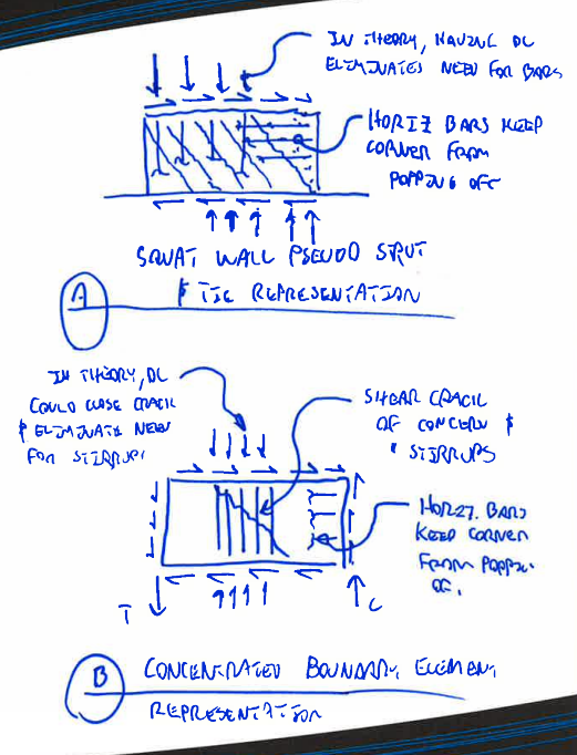
Pls. find attached sketch of a shear wall.

The resisting moment(Mr) is obviously much bigger than the overturning moment. If this is the case,then, wht is the net resulting moment?

Does it mean that the wall will only act generally in "compression"?

Any ideas will be greatly appreciated.
 
 http://files.engineering.com/getfile.aspx?folder=a7f3ef38-32e7-4770-8e86-1951db8eb671&file=overturning_&_resisting_moment.jpg
Replies continue below

Recommended for you

If your resisting moment is larger than your overturning moment it means that your wall is not going to overturn. So, if it is not overturning than that would indicate that there is no uplift acting at the ends of the wall. To determine what the pressure is at either end of the wall you can use P/A plus or minus M/S. When you add the pressure from the moment to the pressure of the weight, that will be the main compression side and your max bearing load. When you subtract the M/S from the P/A that will be the side that wants to lift. If that value is positive, that means that the weight of the wall is more than the uplift force acting on the wall from the moment. See the link below, it shows the stress distribution when the P/A is larger than the M/S.


Also, no your attachment is not visible.
 
Thanks Stenbrook.

My follow-up question is, if the resisting moment is greater than the overturning moment(my attachment showed a 30mx15m high 175mm thk shear wall with hor. load of,ie, 150kN at every 3 meters on the left side of the wall, and 565 kN/m on top of the wall).

if Mr = resisting moment(due to self weight & vert loads), and Mot = overturning moment(due to hor. loads)

in this case, the lever arm of Mr is half the length of the wall(30/2 = 15m)

so, approximately, Mr = ((30x15x.175x25) + (565x30))30/2 = 283781.25 kN.m.

Mot = 150(3+6+9+12+15) = 6750 kN.m., therefore,

net moment = 283781.25 - 6750 = 277031 kN.m., so basically what's this value mean, in terms of designing the reinforcement?
 
that value doesn't mean anything for designing reinforcement, it is just a check for global stability. For designing the wall you take essentially the overturning moment value at each level and design the wall reinforcement for that, plus shear and vertical loads.
 
why I cannot attached document to my post? Is there something wrong?
 
@StrucSU10,

The worst overturning moment is 6750 kN.m(at the base level), but the resisting moment is far greater.

Does it mean, that in designing the reinf., it is purely compression since the overturning moment is "neutralized"?
 
Yes, you will design the boundaries for compression only since there is no tension on them.
 
You've got a pretty squat shear wall there. Therefore:

1) You ought to use squat shear wall design principles.
2) You should consider if your 30m wall will really be two 15m walls with a vertical control joint plane of weakness in the middle.

Neither of these things prevents you from using your resisting dead load of course. They just change the math a bit. If it were me, I'd ignore the dead load for the purpose of designing the distributed vertical wall reinforcement. It probably won't take much, if anything, more than code minimums and you can spare yourself the mental pain of trying to work out how the resisting gravity load gets to where it needs to be in order to eliminate the need for vertical steel.


I like to debate structural engineering theory -- a lot. If I challenge you on something, know that I'm doing so because I respect your opinion enough to either change it or adopt it.
 
Thanks Kootk,

I'm a bit confused, because others designed the reinforcement for the net moment(Moment resisting - Moment overturning) exclusively concentrated on both sides of the wall; it really make sense to me if the overturning moment prevails, but in the case of your resisting moment prevails(huge amount of dead load which nullify the overturning moment), it is in my opinion that the reinforcement areas result should be distributed along the length of the wall since it is really compressive.

But most of the time they just simply tagged it as "Tension/Compression" result and only confined the reinforcment on the edge of the wall(as if whatever the result, it is always on "tension" that's why they coined "tension/compression" along the in-plane of the wall).
 
You're most welcome monchie.

What you've described is very common and, in my opinion, a combination of FEM spawned laziness and a lack of understanding of the fundamentals.

The squat shear wall provisions are basically a poor mans's strut and tie formulation. However, as the free body diagrams show below, the demand for distributed horizontal and vertical steel is nearly identical whether you use squat wall provisions or the the boundary element approach.

Capture_pazceg.png


I like to debate structural engineering theory -- a lot. If I challenge you on something, know that I'm doing so because I respect your opinion enough to either change it or adopt it.
 
Status
Not open for further replies.

Part and Inventory Search

Sponsor