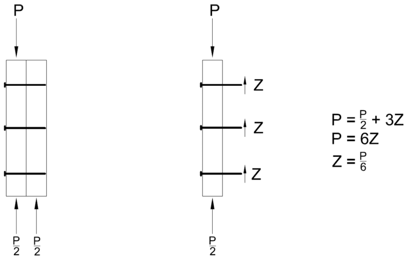
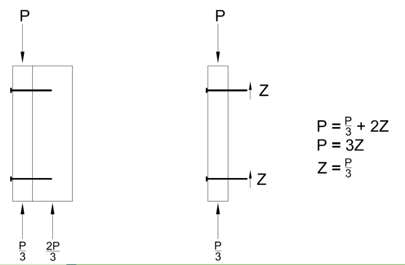
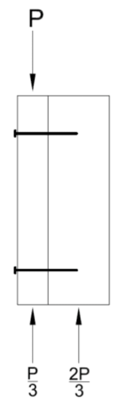
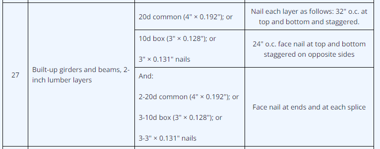
How would you go about calculating the number/spacing of fasteners required to create a multi-ply wood beam such as a 2-2x10 with the 9.25" side vertical and the fasteners horizontal? I'm aware that there are prescriptive requirements for this situation and details provided by manufacturers such as Simpson and Weyerhaeuser, but I'm having a hard time understanding how one would do the calculations. If the multi-ply beam was oriented such that the 9.25" side was horizontal and the fasteners were vertical, one could look at the shear flow at the interface between the beams, but I'm not sure about this situation. My feeling is that fasteners wouldn't matter much if the beam was loaded from the top, but it certainly would if the beam was loaded from the face as with face-mounted joist hangers. Any help is appreciated!
Tek-Tips is the largest IT community on the Internet today!
Members share and learn making Tek-Tips Forums the best source of peer-reviewed technical information on the Internet!
-
Congratulations TugboatEng on being selected by the Eng-Tips community for having the most helpful posts in the forums last week. Way to Go!
Multi-ply Wood Beam Fastener Calculation 1
- Thread starter TAB_HOO
- Start date
Similar threads
- Locked
- Question