Continue to Site

Eng-Tips is the largest engineering community on the Internet

Intelligent Work Forums for Engineering Professionals

  • Congratulations IRstuff on being selected by the Eng-Tips community for having the most helpful posts in the forums last week. Way to Go!

Modelling of OSB panels

Status
Not open for further replies.

kellez

Civil/Environmental
Nov 5, 2011
276
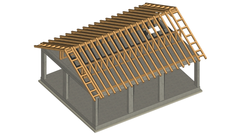
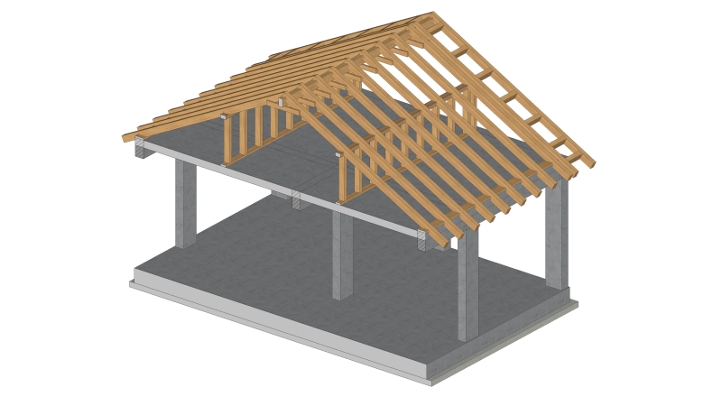
Any thoughts on what is the best way to model an OSB panel? I am modelling a roof with rafters and OSB on top therefore i would like to add the OSB sheathing on my analytical model.
I am thinking of using the the following element

1. Shell elelement -> Orthotropic
Youngs modulus in x direction, Ex = 11000 MPa
Youngs modulus in y direction, Ey = 11000 MPa

2. Thickness = 18mm
3. Material = timber

Any idea what values shall i use for Youngs Modulus?

UPDATE:

The values to be used for the youngs modulus for OSB3 are

Youngs modulus in major axis = 3500 N/mm2
Youngs modulus in minor axis = 1400 N/mm2
 
Replies continue below

Recommended for you

OSB have different characteristics in each orthogonal directions (Ex =/= Ey). When I do this I choose values based on some product (search on internet) to get some standard values and then do analysis based on this. I also make a comment that my calculation is valid for characteristic fmk=, fck=, fvk=, E= or better.
Since OSB panels are orthotropic materials, you have to be careful how you orient them.
 
n3jc said:
OSB have different characteristics in each orthogonal directions (Ex =/= Ey). When I do this I choose values based on some product (search on internet) to get some standard values and then do analysis based on this. I also make a comment that my calculation is valid for characteristic fmk=, fck=, fvk=, E= or better.
Since OSB panels are orthotropic materials, you have to be careful how you orient them.

Great info thanks, i will look into it a bit more.
One more question, do you tend to reduce the value of the stiffness of the OSB due to the nature (nails) of the installation?
Also do you model the whole thing as one shell element that covers the whole side/pitch of the roof or do you model each individual OSB panel according to the dimensions of the OSB panel used for example 2.44mx1.22m?
 
I have done some research and found these data,
for OSB3 these are the minimum requirements set by EC for the youngs modulus. These are the values also stated by the manufucturers

Youngs modulus in major axis = 3500 N/mm2 -> Major axis is the length of the panel (longest side) its also marked on the panel
Youngs modulus in minor axis = 1400 N/mm2
 
How will you model connection between OSB and timber elements? If you just put it over line elements, you will have rigid connections and whole structure will be more stiff than in reality. Proper way would be using spring links between surface and line elements. Stiffness of the links based on fastener stiffness in a osb-timber connection. Eurocode 5 has these values. But I wonder why would you go in so much trouble. What are you trying to calculate? I think you are overdoing it. All this software we nowadays have makes us think we need FEM for every case we get but in fact simple formulas in codes and books are much better.
 
molibden said:
How will you model connection between OSB and timber elements? If you just put it over line elements, you will have rigid connections and whole structure will be more stiff than in reality. Proper way would be using spring links between surface and line elements. Stiffness of the links based on fastener stiffness in a osb-timber connection. Eurocode 5 has these values. But I wonder why would you go in so much trouble. What are you trying to calculate? I think you are overdoing it. All this software we nowadays have makes us think we need FEM for every case we get but in fact simple formulas in codes and books are much better.

You are absolutely right, i didnt think of the connection between the OSB and rafters, i did exactly as you mentioned, I just put it on top of the elements. Well if i have to assign springs to the panels then this will need a lot more work. Maybe I could just decrease the modulus of elasticity of the OSB material in order to take into account the nails.

The main reason i want to model the OSB panels is to capture the stiffness provided to the rafters that make up the roof. After all they do provide a certain amount of stiffness to the timber structure as a whole.
Another reason is to be able to apply the roof coverings load on top of the panel elements (OSB) which makes it a lot easier than calculating the load that applies to each individual rafter.
Also I am modelling the whole structure in one model, the RC frame together with the Timber roof on top. I am doing a seismic analysis therefore i would like to also capture the forces on the timber frame as a result of the seismic analysis.

if you are interested there is more info on the link below regarding my structure


This is the structure I am trying to model

MONASTIRI_-_Final_Roof_Design_4_2_copy_2_vohbc8.jpg


MONASTIRI_-_Final_Roof_Design_2_lzt8x3.jpg


MONASTIRI_-_Final_Roof_Design_5_h3jsfi.jpg
 
I would advise against it. Design the roof and RC structure separately. You are wasting time with so much modelling. Use this time to properly design the details - connections - instead.

Ends of roof seem unstable - last rafter has no support at the bottom.

What is your ridge beam doing - purpose?

Put OSB sheathing on top of rafters, design two shear walls for seismic/wind, design "triangle" with two rafters, two columns and two supports for vertical and horizontal forces, apply all loads to RC structure and carry on. Simple if you don't want to complicate.
 
molibden said:
Put OSB sheathing on top of rafters, design two shear walls for seismic/wind, design "triangle" with two rafters,

As long as the ends of the rafters are fastened to the concrete deck, no shearwalls are required. The roof diaphragm acts as a giant, slanted shearwall for loads parallel to the ridge.
Loads perp. to the ridge are taken out by the shear connections of the rafters to the slab.
 
XR250, that is one way of doing it, but in this case I would probably go shear wall route. Roof diaphragm is nice but I wonder if local contractors even know what that is.
 
molibden said:
Ends of roof seem unstable - last rafter has no support at the bottom.

There will be a 25cm thick gable wall at both ends of the roof, build on top of the RC slab.
The two rafters at each edge of the roof will be directly fixed/anchored to the 25cm thick gable masonry wall.
The gable ladder will also be embedded within the masonry wall. I will also use steel brackets to connect the gable wall to the roof structure.


No-250_11_j2vtse.jpg
%CE%9D250_En_arynpc.png

MONASTIRI_v10_-_Structural_Model_-_33_-_Timber_Roof_Design_3_ScreenShot_24102017_184822_jizbnm.jpg
 
molibden said:
What is your ridge beam doing - purpose?

The ridge beam is there for constructibility purposes, bracing and completeness of the roof,
as you can see the rafters are supported by the RC slab at one end and by the stud wall in the middle, the rest of the rafter is then left to cantilever at ridge level.

There is avery long post on how I have reached this roof design at the post below, if interested

 
Status
Not open for further replies.

Part and Inventory Search

Sponsor