Continue to Site

Eng-Tips is the largest engineering community on the Internet

Intelligent Work Forums for Engineering Professionals

  • Congratulations KootK on being selected by the Eng-Tips community for having the most helpful posts in the forums last week. Way to Go!

Middle plane orientation

Status
Not open for further replies.

gabimo

Mechanical
May 2, 2013
124
Will the orientation of the side faces of a cube to the bottom feature control the orientation of the middle plane to the bottom feature

ASME Y14.5-2009

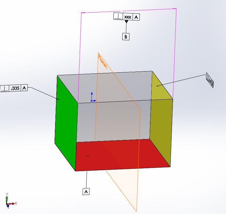
Picture a parallelepiped / cube (regular feature of size):

If two side faces (both) are perpendicular to the bottom face within some tolerance (let’s say .005 and .008 respectively---from the raw material), the width (the distance between them) is controlled by a size tolerance (let’s say .012—also from raw material), then the question is what is maximum perpendicularity error allowed between the middle plane and the bottom surface. The part has datum feature A = bottom face and datum feature B, secondary = the .012 width, oriented within some amount (the one I am trying to get the maximum value) to primary datum feature A

If picture is needed, please let me know.
 
Replies continue below

Recommended for you

Will the orientation of the side faces of a cube to the bottom feature control the orientation of the middle plane to the bottom feature
The orientation of the side faces may or may not control the middle plane's orientation. They certainly impact the middle plane, but it depends on whether the side faces tilt in the same direction. Sometimes their orientation will cancel each other out -- resulting in no impact on the middle plane's orientation -- and sometimes their orientation will be in the same direction -- resulting in a center plane that deviates from the ideal.

John-Paul Belanger
Certified Sr. GD&T Professional
Geometric Learning Systems
 
Capture_middle_plane_nx49vj.jpg


Green face perpendicular within .005 to red.
Yellow face perpendicular within .008 to red
Green to yellow within .012
Plane 1, datum feature aligned with the size dimension.

Plane 1 to red orientation within???
 
J-P and/or everyone,

I am curious myself, why the "maximum perpendicularity error allowed" (as requested) cannot be mathematically calculated?
What could be the worst case?
 
"Perpendicularity" only means that tolerance zone is perpendicular to the datum.

Within that tolerance zone the surface can take any form and shape imaginable.

How to pick "worst case" out of infinite number of possibilities?

"For every expert there is an equal and opposite expert"
Arthur C. Clarke Profiles of the future

 
CH,
Based on the configuration shown, do you really think that the perpendicularity of the middle plane (datum B, driven from the two side faces) to the bottom face (datum feature A) can be any amount? In other words, it is not limited to anything?
Just curious.

 
Are you talking about perfect or imperfect median plane?

Either way it will be limited to something you specify on the drawing.

"For every expert there is an equal and opposite expert"
Arthur C. Clarke Profiles of the future

 
Oaky. Let’s say datum reference frame of the shown part is A, primary and B secondary.
A= the bottom face
B= the middle plane (RFS)

The part is assembled (with its mating components) based on datum feature A primary and datum feature B secondary (RFS) . The coordinate system for this part is A primary and B secondary (DRF: A and B)
When the part is defined on the drawing: A become primary and B - (as a secondary datum feature secondary) - should be oriented to A, correct?
The appropriate callout would be perpendicularity within some amount (functionally amount ) to A (primary).

Let’s pretend, for a second, that the functional amount for perpendicularity between primary A and secondary B is determined. Known number (let’s say came from research and development)
The question is: if the functional amount is bigger than the “calculated” one (the one limited by the two perpendicularities to the bottom face and maybe the size requirements/ width) then the perpendicularity of B to A is useless.
Am I correct? Or am I missing something?

Are you going to add it on the drawing or rely on the “calculated” amount (since this amount is more restrictive anyway). Probably, the OP question (and my question too) is what is that amount = that point of diminishing returns.
 
To my understanding: since the "datum B" feature is a width FOS at RFS (Rule #2), the center-plane that must fall inside the two parallel planes of the perpendicularity tolerance zone is defined by the center-plane of the RAME - two parallel planes perpendicular to datum A that simultaneously contact the two vertical sides at the minimum width. Given this, the perpendicularity of the two sides individually are independent controls that have no impact on the finding the center-plane with the RAME. Additionally, the "datum B" width must only meet size and from (Rule #1) requirements.

Certified Sr. GD&T Professional
 
I may be mistaken, but would say that even if the considered geometry is ridiculously simple, the task to analytically calculate maximum possible perpendicularity error of the center plane of width B relative to A is quite complex (at least too complex for me). One should consider not only rotation of sides faces about z axis within their respective perpendicularity tolerance values, but also possible twists of the surfaces and the tolerance zones about y axis (here width tolerance may come into play).

mkcski,
For the perpendicularity callout applied to a width FOS, the callout controls orientation of unrelated actual mating envelope of the FOS (UAME), not RAME. RAME, by definition, is perfectly related (oriented) to applicable datum(s) - datum plane A in this case - thus has 0 perpendicularity error to datum plane A. Center plane of RAME is nothing but the datum plane B in this case.
 
pmarc,

If for you is too complex.............can you imagine what is for me. [dazed]
 
Like I said, I may be mistaken. Perhaps someone will show you in a minute a way to easily calculate it.
 
@greenimi:

You were the first to use the word "mathematical"

Unfortunately, even when things look simple on the surface, establish solid mathematical proof that will satisfy infinite number of possibilities, may not be a trivial task.

That's why I keep saying over and over again: if you see something is unclear or ambiguous just apply appropriate control directly to it. Don't expect everybody out there to appreciate highly sophisticated but confusing approach.

"For every expert there is an equal and opposite expert"
Arthur C. Clarke Profiles of the future

 
pmarc:

Your ability to communicate GDT in words is far superior to mine. Until I recently found this forum, I did very little written communication wiht GDT. I was trying to say what you so clearly described. Please excuse any confusion I may have caused others.

Certified Sr. GD&T Professional
 
Status
Not open for further replies.

Part and Inventory Search

Sponsor