MattEdwards and donatim24, I guess the use of a position symbol isn't required, but ASME Y14.5 (the standard for dimensioning and tolerancing here in the US) says that if traditional coordinate dimensioning is used to locate features, then it has to be done "from two or three mutually perpendicular planes" (paragraph 4.6.1). That sure sounds like datums need to be invoked, and I'd say that their order of precedence needs to be indicated.
That same standard also discusses this problem of ambiguous direction/orientation in its Appendix I, on pages 306-307.
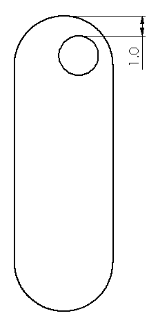
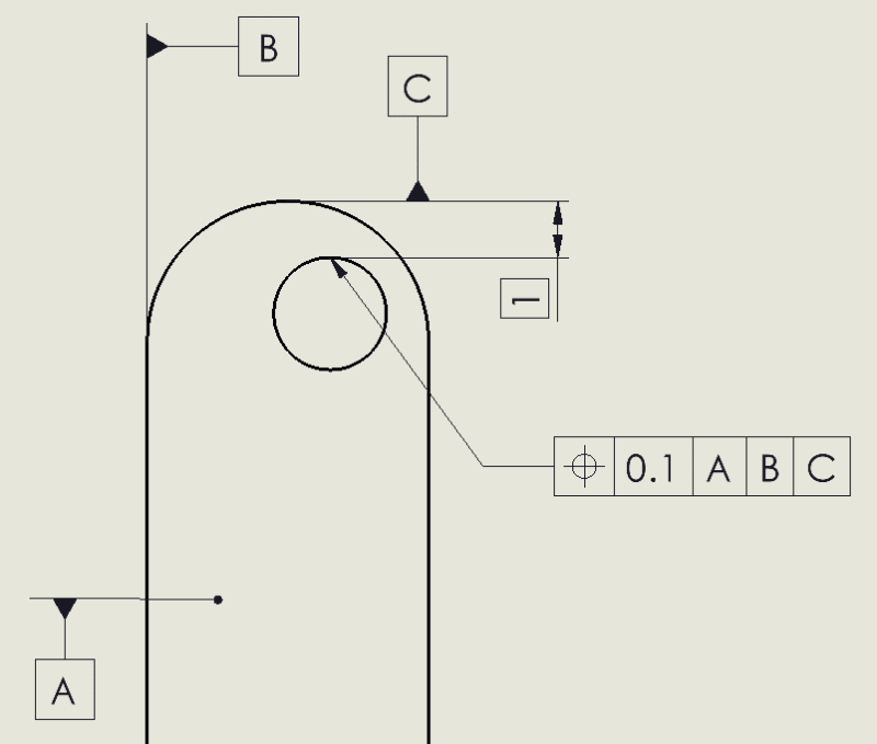
Therefore, some sort of GD&T-style datums should be labeled to clarify that the distance is to be taken in a direction parallel to one of the long edges. Matt, your situation poses a curveball because you want to control the edge of the hole, not the axis (which is typically how the position symbol works). Some folks might suggest a profile tolerance, but I think a good option might be to keep the A, B, C datums as you've already labeled them, but keep your original number of 1.0 (without a box around it). Then add a note -- either a blanket note for the drawing or one specific to that dimension -- saying "dimension(s) to be measured from datums A, B, and C in that order of precedence." The result is a hybrid of traditional and GD&T styles, but it would remove any ambiguity.