Tek-Tips is the largest IT community on the Internet today!

Members share and learn making Tek-Tips Forums the best source of peer-reviewed technical information on the Internet!

  • Congratulations JAE on being selected by the Eng-Tips community for having the most helpful posts in the forums last week. Way to Go!

Mesh singularity on non-manifold geometry

IcarusAero223

Aerospace
Joined
Mar 10, 2024
Messages
12
Hello everyone!

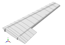
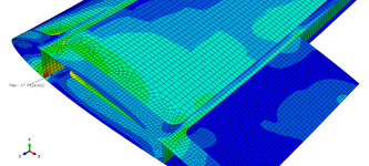
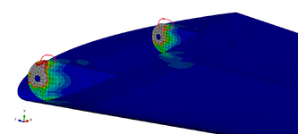
I'm modelling a composite wing and am exhibiting a mesh singularity at the spar web/cap connection.

Solutions I've tried:
  1. Modelling softer boundary conditions through springs
  2. Reducing the stiffness of the spar webs
  3. Pulling out spar web surfaces and modelling BC's through idealized bolted contact
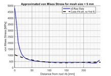
One of the options is to ignore the singularity by averaging the stress in n amount of elements before the singularity by measuring and graphing which I did, but I'm not so sure how accurate that would be as per my lack of experience.

And as you can see none of it really worked so I decided to come here and see if anyone has an answer to this little problem I have.
I'm assuming the fix might not be the modelling approach but rather geometry modification and for that I have no more ideas unfortunately.

Any help is appreciated! [bigears]


wing_geometry.pngflat_encastre_singularity.pngrounded_flange_singularity.pngmises_plot_mesh_sizes.jpgfitted_mises_plot.jpg
 
You could use submodeling or shell-to-solid coupling to model that small region with solid elements and including some fillets thus obtaining more realistic result.
 
You could use submodeling or shell-to-solid coupling to model that small region with solid elements and including some fillets thus obtaining more realistic result.
Thanks for the suggestion FEA way.

As the wing is supposed to be optimized later in regards to ply thicknesses and orientations, using any solid elements might not be the most ideal solution.

Could the problem be in the mesh connectivity? I did check for free edges and it seems OK at the moment.

And one important thing to mention is that the wing is fixed at the root rib.
 
As the wing is supposed to be optimized later in regards to ply thicknesses and orientations, using any solid elements might not be the most ideal solution.
There are also composite sections for solid elements so you can use layups with them. This is often used e.g. when analyzing nozzle regions of composite pressure vessels.
 

Part and Inventory Search

Sponsor

Back
Top