Tek-Tips is the largest IT community on the Internet today!

Members share and learn making Tek-Tips Forums the best source of peer-reviewed technical information on the Internet!

  • Congratulations cowski on being selected by the Eng-Tips community for having the most helpful posts in the forums last week. Way to Go!

Long Span Concrete Girder 2

Status
Not open for further replies.

simplespan1

Structural
Joined
Dec 1, 2020
Messages
2
Location
US
Is there any guidance for mild reinforced concrete with long span? Examples I can find always involve prestressed beams, but is it possible to design a heavily reinforced (non-prestressed) concrete beam spanning 45'-60' supporting heavy uniform loads (20 klf), if beam size is not limited (10' deep beam)
 
The span length is likely to be controlled by two factors - deflection limit, and end shear capacity.
 
20 klf is a pretty significant load.

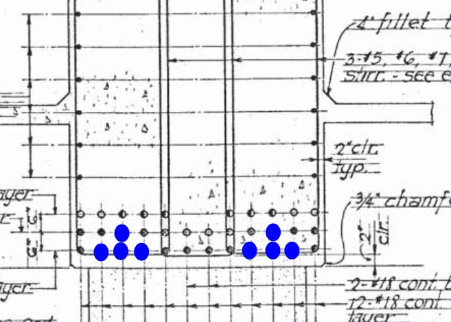
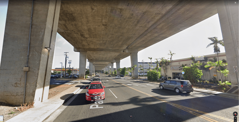
With that being said, it's totally possible! There are a lot of straddle bent caps in bridge design that support over 20 klf and are designed using conventionally reinforced concrete. I've designed several in the past. Currently designing one for a 45ft span. I've analyzed lots. Check out this bridge design back from the 1970's that utilizes conventionally reinforced concrete bent caps. You can't see all of it since the superstructure and bent cap are integral but those are 10ft deep bent caps and if memory serves me correctly is carrying more than 20klf. Those are 12ft traffic lanes and 8ft sidewalks so total centerline column to centerline column is about 75ft. The cap is just loaded up with several rows of #11 #18 Grade 60 mild reinforcing.

So yes, has been done and can still be done without post tensioning. I don't think you need any guidance other than the applicable code you are following for your structure design.

What is your project regarding? What is the source of the load?

Paiea_wesjqn.png
 
STrctPono

That is very helpful. Have you used any significant software, or is the design a result of traditional bending shear and deflection checks that can be done by hand? This girder would carry building loads from multiple floors above. For 75' that must have required a ton of #11's and stirrups and the end cols look about 5'x5'.


Traditional bending, shear, and deflection checks by hand. Like I said, 10ft deep and I believe 8ft7ft wide. When I get into the office I will post the cross section of the cap to clarify any of my misstatements.

Straddle bent does have end fixity with the columns so it does behave like a frame, but this is to be expected.
 
Work out required sectional area through deflection limit.
Let W = 20 klf, L = 75', fc' = 6000 psi E = 57√fc' (ksi), Δ ≤ L/300 (in)

Δ = 5WL4/384EI ≤ L/300 ---> I ≥ 1,075,000 in4 = bh3/12
Let h=3b, I = 2.25b4 ≥ 1,075,000 in4 ---> b ≥ 26.3", use 27", and h = 3*27 = 81"

Let d ≈ 0.9h = 73"
WD = 150*27*81)/144000 = 2.3 klf
Wu = 1.4*2.3+1.6*20 = 35.22 klf, say 36
Vu = 36*75/2 = 1350 kips
øVc = 0.75*2*√6000*27*73/1000 = 229 kips
Vs = Vu-øVc/ø = (1350-229)/0.75 = 1495 kips
Vsmax≤ 8√fc'bd = 8√*6000*27*73/1000 = 1221 kips < Vsreq =1495 kips NG --> Increase beam size and fc' to make up the deficit. Ideally, the Vsmax should be kept within 6√fc'bd to avoid congestion of steel.

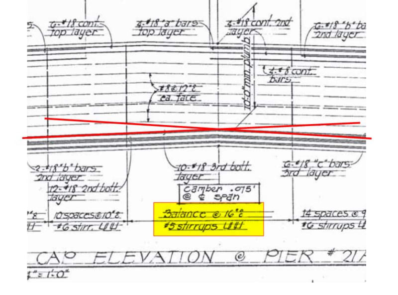
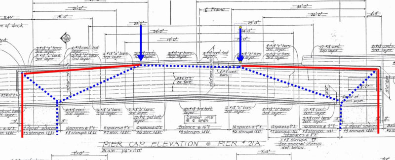
 
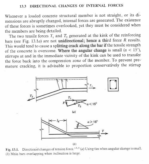
Sweet old drawing, thanks for sharing that. I'm curious: is the kink in the bottom steel not a rather serious detailing faux pas? Or is there some bridge world allowance for this kind of thing when the angular change is kept low enough etc? I'm always up for learning a new trick.

J01_ziesor.jpg
 
KootK,

Don't you know, bridges operate in a different physical realm that obeys different laws of physics and engineering than buildings!?

Good catch on the detailing. The bend in the bottom bars is certainly in juxtaposition to how I was taught to detail. With a bit more carefully placed stirrups acting as anchors, I could be ok with the detail but I would not detail it that way if it were me. I have never detailed a straddle bent with a kink in the middle and based on the impression of the OP's project, I doubt he will be either.

Your proposed detail certainly has merit but would be very difficult to install given the level of rebar congestion. I may never know how they actually constructed it in the field. The set of plans I have is supposedly as-built drawings but there are very few field markings.

Bridge has been standing with no issues since 1976 so perhaps that "straightening" behavior is not as significant as we were taught to believe.
 
STrctPono said:
Don't you know, bridges operate in a different physical realm that obeys different laws of physics and engineering than buildings!?

I myself am but a collapsed wave function feigning consciousness.

StrctPono said:
Bridge has been standing with no issues since 1976 so perhaps that "straightening" behavior is not as significant as we were taught to believe.

There's that. But, then, that data point really needs to be paired up with the why of it. Unless the underside of those bents is all cracked up, the positive moment steel hasn't really been mobilized and the detailing faux pas hasn't had a chance to really make its presence felt. Given the common proportions and detailing of these kind of things, I feel that there's really a pretty capable arching mechanism in place during the early to moderate stages of loading.

C01_qqv93f.jpg
 
I wouldn't call it a detailing faux pas. Typical scenario for a bridge with 2% two-way crossfall, the total bend in those bottom bars would be about 2.3 degrees. The force required to resolve the straightening tendency would only be ~4% of the force in those bars. A single well-positioned stirrup would be able to account for this pretty easily. Even if the stirrups were placed somewhat haphazardly (i.e. not directly at the kink), I don't think this would make much difference. The bottom bars are pretty large diameter and therefore probably stiff enough to engage a number of stirrups around the kink.

Even in a slab with no shear reinforcement, I suspect that the tensile strength of the concrete alone would be enough to prevent the bottom bars from blowing out, but that's just a gut feeling.
 
gusmurr said:
A single well-positioned stirrup would be able to account for this pretty easily.

I'm getting three, six leg stirrup sets. Which would be fine if they were set up like that right at the knuckle in a fan or whatever. As it stands, you'd need to distribute the kick out to about 32" of stirrup spacing. And even at that it's probably wishful thinking that you're actually restraining the bars shown in blue below.

c02_vhpels.jpg


C01_wnbzdl.jpg
 
I agree with your analysis KootK.

Personally, I don't see the 16" spacing as being too much of an issue, especially considering these are #18 bars and over that distance would have considerable flexural stiffness just by themselves. At overload, I would think that with some cracking and localised deformation of all those bars, the whole system would find a way of resolving all those forces pretty easily.

If the alternative is to provide a lap (perhaps 2 m long?) with 34 of those bars, I think what is drawn is really the best option. Reducing the spacing around the change in angle is probably a good idea overall.
 
I'd be pretty reluctant to rely on the longitudinal bars spanning between spaced stirrups. It wouldn't take very much deflection in the bars before deformation compatibility would dictate that you'd spall the concrete around them and expose the bars to corrosion potential at a critical location. If the longitudinal bars had a gentle radius and the stirrups landed along the radius, that would be a bit different.
 
Fair enough point. I would only say that if we were in a situation where the concrete spalled and the bars were exposed, we might be talking about a pretty extreme ULS event, so perhaps this isn't of too much importance. From the fuzzy photos above, it seems that these headstocks are in reasonable shape after 50 years of service. A separate SLS check of that region to ensure that little to no cracking would occur would probably be a good idea.

My overall belief is that at ultimate conditions, RC structures are generally a lot more robust and probably have a fair amount more reserve capacity than we would normally give them credit for in design. Things like arching action (as shown above), the ability of the tensile strength of the concrete to resist the bar blowout effect we're talking about, the ability of the large diameter bars to span between spaced stirrups, over-strength of reinforcement that often goes well beyond what is normally required by codes for reliability purposes, etc. etc.
 
Status
Not open for further replies.

Part and Inventory Search

Sponsor

Back
Top