Continue to Site

Eng-Tips is the largest engineering community on the Internet

Intelligent Work Forums for Engineering Professionals

  • Congratulations KootK on being selected by the Eng-Tips community for having the most helpful posts in the forums last week. Way to Go!

Joist Reinforcement

Status
Not open for further replies.

RFreund

Structural
Aug 14, 2010
1,885
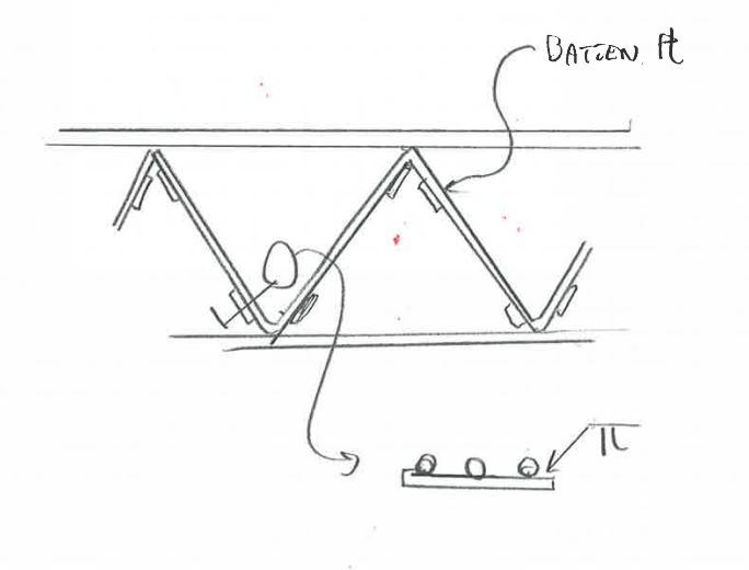
I typically like to reinforce existing joists with the detail that I have attached. It is a little different than just reinforcement the top/bott chords and web members in that it doesn't directly reinforcement the webs. Rather it uses additional web members. Now the analysis that is typically used in these cases, is an analysis using the existing geometry and section to determine the forces in the chords/webs. Then reinforcement is provided to enhance the member section properties. The problem usually is - the shear forces still need to be transferred through existing welds. The attached detail does not rely on existing welds as the new webs are welded to the new chords.
Does the "traditional" approach still seem valid. Meaning if you solve for the force in the chords - reinforcement the top/bottom chords appropriately based on the new built up section. Then size the new web member to take its share of the web force and transfer this into the top/bottom chord? Part of thinks this approach is fine, but part of me thinks the detail looks more like the situation of a flitch beam where the new "truss" will take load in proportion to it's stiffness. In which case the point of where to discontinue the reinforcement seems to get cloudy. Maybe I am over thinking this...

LINK

EIT
 
Replies continue below

Recommended for you

Because you have two independent sets of web members, these will share the load between them in relation to their stiffness. The reinforcement to the chords is welded to the chords so this acts as a single member now. To model it you would have to model the new chord with its combined properties and 2 independent sets of web members attaching to it. You could do 2 models, one with the combined chord and the original web members and one with the combined chords and new web members. The ratio of the stiffness of the 2 models would tell you how much load would be taken by the original and new web members.
 
I'm quite interested in this as I've long wanted a method for circumventing existing weld checks. You may indeed have a better mouse trap on your hands here Mr. Freund. I shall put you through your paces before signing off however. My thoughts:

1) As phuduhudu mentioned, the top chords will be composite members rather than parts of independent trusses so it should be business as usual there.

2) I think that what changes about the webs is the reinforcement philosophy. Normally, our strategy is to reinforce the web members such that they can take the increased load. Here, the strategy will be more like what we do with the chords where we often reinforce with an element of sufficient stiffness that it will effectively "shield" the existing member from seeing more load than it was originally designed for. You'll want to ensure that your new webs are stiff enough that they are effective in drawing shear away from the existing webs and, more critically, the existing welds. Web members sizes will have a negligible impact on cost here. I'd calculate the stiffness that you need and then provide 50% more than that.

3) For all to be kosher, I have a sneaking suspicion that you require a means of transmitting vertical shear between the existing and new truss systems. As it stands, you're ability to do that seems dubious. You could transfer some joint shear via the connections between the new chords and the existing chords at the panel points I suppose.

4) Your new top chords are relatively slender elements. Can you prevent them from local/LTB buckling when in compression?

5) Your new webs will be entirely eccentric to your new chords. Perhaps this is not a big deal given the narrowness of your new chords.

6) Your new chords will be quite eccentric to your existing chords. I guess that's just math.

7) I'm curious why you chose to install the new webs on the inside of the new chords. Installed in the air, it seems as though it would be much easier to install the new webs on the outside of the new chords.

I like to debate structural engineering theory -- a lot. If I challenge you on something, know that I'm doing so because I respect your opinion enough to either change it or adopt it.
 
OK, here goes a first response:

KootK said:
1) As phuduhudu mentioned, the top chords will be composite members rather than parts of independent trusses so it should be business as usual there.
Agreed.

KootK said:
2) I think that what changes about the webs is the reinforcement philosophy. Normally, our strategy is to reinforce the web members such that they can take the increased load. Here, the strategy will be more like what we do with the chords where we often reinforce with an element of sufficient stiffness that it will effectively "shield" the existing member from seeing more load than it was originally designed for. You'll want to ensure that your new webs are stiff enough that they are effective in drawing shear away from the existing webs and, more critically, the existing welds. Web members sizes will have a negligible impact on cost here. I'd calculate the stiffness that you need and then provide 50% more than that.
This is where I'm having difficulty deciding how to handle this. The new webs are welded to the new chords. The new chords will transfer the shear into the new webs. Is this based on the stiffness of the new chords and webs as a built up element or just purely the PL/AE stiffness of the web member? If the new chords were not welded to the new webs then everything would be based on relative stiffness (and you'd have a couple of point loads at the end of the new "inserted" truss to deal with, but let's not sidetrack).

KootK said:
3) For all to be kosher, I have a sneaking suspicion that you require a means of transmitting vertical shear between the existing and new truss systems. As it stands, you're ability to do that seems dubious. You could transfer some joint shear via the connections between the new chords and the existing chords at the panel points I suppose.
Again I this situation isn't clear to me. I'm thinking all of the shear is basically transferred in this fashion; isn't that the case with any truss? I'm missing something here...

KootK said:
4) Your new top chords are relatively slender elements. Can you prevent them from local/LTB buckling when in compression?
I suppose they are somewhat slender depending on how you look at it. If it is 4"x3/8" then local is not bad. If you say it is unbraced about its weak axis then you are at about L/r = 181 but it would be intermittently welded to the top chord, so i think you are ok, no?

KootK said:
5) Your new webs will be entirely eccentric to your new chords. Perhaps this is not a big deal given the narrowness of your new chords.
Yeah that is true. I suppose you could account for this bending moment = Fweb x (t.web/2+t.chord/2) ?

KootK said:
6) Your new chords will be quite eccentric to your existing chords. I guess that's just math.
I'm not understanding this eccentricity problem... you have basically two built up channels.... now I'm even confused if my response to #5 is correct...

KootK said:
7) I'm curious why you chose to install the new webs on the inside of the new chords. Installed in the air, it seems as though it would be much easier to install the new webs on the outside of the new chords.
I think originally there was weld to the existing and the new. Especially if the bottom chords we angles.

Here is some background as to where this began:

I'm surprised I can't find anything in SJI's design guide. They sort of address this with suggesting gussets where additional weld is needed.


EIT
 
Dull Stuff

OP said:
I suppose they are somewhat slender depending on how you look at it. If it is 4"x3/8" then local is not bad. If you say it is unbraced about its weak axis then you are at about L/r = 181 but it would be intermittently welded to the top chord, so i think you are ok, no?

You're definitely braced for weak axis buckling. I was more thinking of torsional buckling in the top chord. The top weld will provide some rotational restraint, and you don't need much. Of course, the top weld is one sided which is a little unnerving.

OP said:
Yeah that is true. I suppose you could account for this bending moment = Fweb x (t.web/2+t.chord/2) ?

Eh. In practice I probably wouldn't bother. The eccentricity is small and the connections to the existing joist should restrain lateral movement. I'd be worried without the lateral restraint because, with such a slender member, you might get P-delta stuff going on. When all is said and done, I wouldn't mind seeing the bottom chord braced back to the next joist intermittently somehow.

OP said:
I'm not understanding this eccentricity problem... you have basically two built up channels.... now I'm even confused if my response to #5 is correct...

The centroids of your new chord members are substantially lower than the centroid of your original chord members. This means that your truss is effectively shallower and the existing web joints will come in above the effective chord centroid, introducing some chord moments. This is one of the arguments for using rods or nested angles for chord reinforcement. They don't change the composite chord centroid location much. This isn't a deal breaker by any means, just something that caught my eye.

The Interesting Stuff

OP said:
his is where I'm having difficulty deciding how to handle this. The new webs are welded to the new chords. The new chords will transfer the shear into the new webs. Is this based on the stiffness of the new chords and webs as a built up element or just purely the PL/AE stiffness of the web member? If the new chords were not welded to the new webs then everything would be based on relative stiffness (and you'd have a couple of point loads at the end of the new "inserted" truss to deal with, but let's not sidetrack).

I agree, this isn't obvious to me at all. I feel that it would be based purely on web PL/AE. Consider a mental experiment with me:

1) For some strange reason, this wasn't a retrofit but you decided to construct your truss this way anyhow (reinforcement and all).

2) Each "web" was really comprised of three members (original web + 2 new rods).

3) Let's talk pure truss behavior. None of the chord continuity nonsense.

Would the properties of the built up chords affect the forces developed in the webs? They would not. The truss, including the three component webs, would be statically determinate. The forces in each three piece web would just be whatever they are. And from there, it seems a natural extension to assume that the force in each of the three components of the web would be apportioned based on PL/AE component stiffness.

Another way to look at this is by studying the movement of the panel point joints at either end of a given three component web. The horizontal movement components of both joints are the same for all three "trusses". The interconnection between the old and new chords assures that. And the vertical movement components of both joints are the same for all three "trusses". The interconnection between the old and newchords also assures this (this is where my concern for vertical force transfer between trusses at panel points comes from). All this means that the axial strain in the three components of each web is the same. And that implies load sharing based on relative axial stiffness.

I like to debate structural engineering theory -- a lot. If I challenge you on something, know that I'm doing so because I respect your opinion enough to either change it or adopt it.
 
OP: "Then size the new web member to take its share of the web force and transfer this into the top/bottom chord?"

Would sizing the new web member and its welds to take the total design web force dodge your concerning issue?
 
Triangled said:
Would sizing the new web member and its welds to take the total design web force dodge your concerning issue?

Now that's an interesting proposal. It would be simple and more or less cost neutral. My only concern would be that, unless you reinforced the whole truss and built new seats, you'd need to transfer all of the shear back to the original truss at some location. Again, this comes back to my concern for localized vertical shear transfer between new and existing. Perhaps this could be got around by doing a direct, new web to old web axial force transfer at the last reinforced web. That would be slick.

I like to debate structural engineering theory -- a lot. If I challenge you on something, know that I'm doing so because I respect your opinion enough to either change it or adopt it.
 
if the new web is sized for full design loads and attached with welds sized for full design loads to the chord, wouldn't 'all' the load be in the web and then 'all' the load in the chord as needed, whether the existing unreinforced chord or the newly reinforced composite chord?
 
Triangled said:
if the new web is sized for full design loads and attached with welds sized for full design loads to the chord, wouldn't 'all' the load be in the web and then 'all' the load in the chord as needed, whether the existing unreinforced chord or the newly reinforced composite chord?

Indeed it would be, right up until the reinforcing ended and all of the shear had to be transferred back to the original joist webs or directly to the joist support. Say, for instance, that you reinforced only the middle third of a joist in the manner proposed, essentially disregarding the existing joist webbing entirely where reinforcement was installed. From a shear/webbing perspective, you'd essentially be hanging the new trusses from the existing truss at the 1/3 point transitions. It's that "hanging" that requires some attention in my estimation. However, I think that there's a solution to that as I mentioned in my last post.

I like to debate structural engineering theory -- a lot. If I challenge you on something, know that I'm doing so because I respect your opinion enough to either change it or adopt it.
 
some challenges in my mind in performing the web relative stiffness method, as I understand it (or misunderstand it) that lead me to seek something different:
1. i'd like to specify the same web reinforcement sizes throughout to avoid field confusion, not to mention office confusion
2. as I understand it, joist fabricators often create the rod webs for the joists in "v" or "w" patterns, rather than one long continuous same size zizgzag from left end to right end. Thus a group of 2 or 4 webs may be, say 3/4" dia followed by a group of 2 or 4 webs at 11/16 followed by a group of 2 or 4 webs at 5/8" or whatever, maybe depending on the stock readily available in their shop, necessitating stiffness calculation adjustments along the length of the joist.
3. as I understand it, joist manufacturers are only obligated to provide enough weld for the design, so that theoretically anyways, the web could not be counted on to support its full section capacity. I worked on some girders awhile ago whose web capacity exceeded the actual weld provided capacity. Not sure how to figure that into a relative stiffness scenario.
 
I believe that SJI now mandates a certain amount of weld overstrength. The relevance of that would depend on the SJI standard in effect when the joist was fabricated.

I like to debate structural engineering theory -- a lot. If I challenge you on something, know that I'm doing so because I respect your opinion enough to either change it or adopt it.
 
What about this 'thought experiment'

1. Let's say we preassemble our new truss (weld the new webs to the new chords). Then we place it in the existing truss with no connection. Then the trusses will take load in accordance with their stiffness. There is the need to transfer forces at the ends of the new truss.

2. Let's say we only need to reinforcement for moment, so we add the plates to the top and bottom chords like I show in the detail. This is normal practice - develop the ends of the chord reinforcement, size a weld based on VQ/I and make sure it doesn't buckle.

3. Let's say we only need shear reinforcement. So we only add web members. We add them along side the existing web member and weld them to the existing chords. Everything still normal here? Would the webs just take PL/AE?

3.a - Lets say the existing geometry doesn't work well to weld these new webs to the existing chords so we add some gussets plates to make things easier. Now lets call these gusset plates the chord reinforcement and you are back to the original detail, no? maybe?

EIT
 
So far, my conclusions are these:

1) I think that the "separate trusses" concept should be abandoned altogether. Due to the nature of your details, all panel points of the "new truss" will be married to the panel points of the "old truss" with regard to both horizontal and vertical displacement. That implies that, at the end of the day, the reinforced truss will just, indeed, be one truss. The individual truss members between panel points will share load based on relative axial stiffness but the individual trusses, taken as whole entities, may not.

2) Like any truss, we can deal with chord design and web design independently because the forces used in both are statically determinate for pure truss action.

3) As I've been espousing, I believe that the critical design issue is the transfer of vertical shear laterally between the old webs and the new webs. Somehow, any shear present in the new webs has to be transferred there from the existing webs. As it stands, you would be accomplishing that transfer through the chords which raises some concerns for me WRT the strength and stiffness of that load path.

I've been thinking about how I might want to accomplish the lateral transfer of vertical shear. The detail below is what I came up with. I like it but it might actually be more work than just reinforcing the welds. And that kind of brings me full circle back to thinking that maybe the traditional approach of reinforcing the webs is preferable to sistering new webs along side of them.

I still think that Triangled's proposal has legs though. Essentially, it represents the wholesale abandoning of the existing webs.

CAPTURE_yzzd3c.jpg


I like to debate structural engineering theory -- a lot. If I challenge you on something, know that I'm doing so because I respect your opinion enough to either change it or adopt it.
 
KootK -

I kinda get what you are saying and I do agree with Triangled's approach of designing the entire load. However, a couple additional questions:

Why are you trying to assist the vertical shear into the new web members? What if the new webs were directly welded to the existing chord, would you still want to provide the battens?

EIT
 
RFreund said:
Why are you trying to assist the vertical shear into the new web members? What if the new webs were directly welded to the existing chord, would you still want to provide the battens?

If lateral vertical shear transfer can be accommodated along a relatively stiff path at the panel points then, no, I would not be pursuing the battens. The question, in your case, is whether or not you have such a load path. At the top, vertical shear would need to be transferred from existing webs to new webs via chord angle leg bending near the panel point. At the bottom, the path delivering shear through the bottom chord rods would be considerably stiffer. But then you'd introduce some weird forces in your welds as the chord rots attempted to roll over.


I like to debate structural engineering theory -- a lot. If I challenge you on something, know that I'm doing so because I respect your opinion enough to either change it or adopt it.
 
Status
Not open for further replies.

Part and Inventory Search

Sponsor