Hello all,
Sorry if this is not the best forum to use, but I'm not sure where else to find bearing experts.
I would love to receive some direction on how one would incorporate bearings into this (not sure what to call it)...
(I hope the .gif file animates ok)
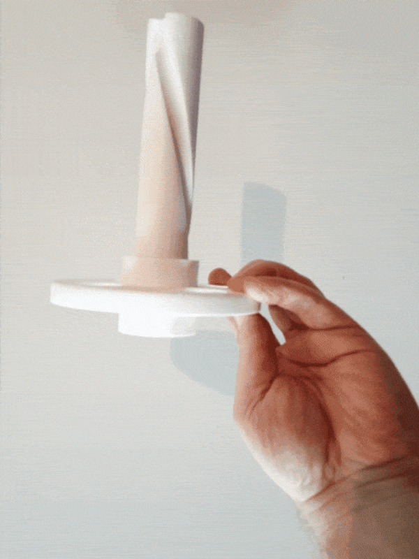
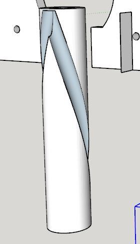
As can be seen, this is a shaft which will rotate 180 degrees, always in the same direction, each time the hub is moved back and forth along the length of the shaft (totaling 360 degrees).
I'm not a mechanical engineer and I have never incorporated bearings into any of my designs previously, so I apologize if this is a stupid question.
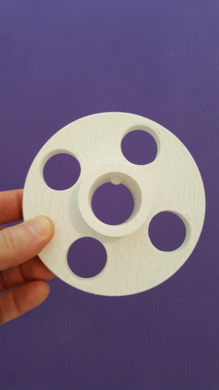
I assume I could place bearings in the front and back of the hub, but I'm concerned that as the bearings cross the helical channel that they may get hung-up. Is that just wrong? If not, what's the solution?
Thanks kindly!
Trip
Sorry if this is not the best forum to use, but I'm not sure where else to find bearing experts.
I would love to receive some direction on how one would incorporate bearings into this (not sure what to call it)...
(I hope the .gif file animates ok)
As can be seen, this is a shaft which will rotate 180 degrees, always in the same direction, each time the hub is moved back and forth along the length of the shaft (totaling 360 degrees).
I'm not a mechanical engineer and I have never incorporated bearings into any of my designs previously, so I apologize if this is a stupid question.
I assume I could place bearings in the front and back of the hub, but I'm concerned that as the bearings cross the helical channel that they may get hung-up. Is that just wrong? If not, what's the solution?
Thanks kindly!
Trip
![[smile]](/data/assets/smilies/smile.gif "[smile] [smile]")