@mfgenggear
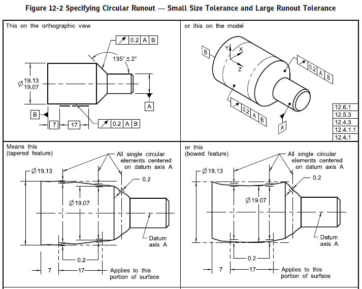
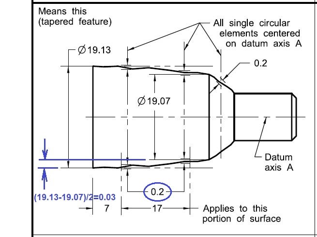
When verifying runout, the dial indicator reading includes several types of part errors: form, orientation and location(axis offset). Your figure shown is an error of axis offset, my question is on the form error, how to interpret the "Means this"? how can a 0.2 tolerance floating within a 0.03 tolerance zone? The figure shown on the "Means this" is not easily visualized for me. Anyway, thanks for the picture posted.
@season lee
@Brurunduk has clearly answered the question, however I will give my answer in laymen terms.
in order meet the requirement if the two diameters were in theory perfect cylindrical diameters the full runout could be utilized.
being this is not a perfect world and there are errors in the roundness and taper, now the runout has to be held tighter.
so other words all inclusive. from the theoretical these are maximum allowable errors, in the real world
the machinist has tricks up his sleeve. he would turn these diameter to obtain the designers requirements.
he or she would hold the diameters with the least amount of errors. but take into account he can & will use the maximum tolerance allowable.
even thou the authors never provide manufacturing centers it is a common mfg method for cylindrical parts with tight total runout
and runout, pretend that the " mean this " had centers it is now easier to verify runout on both diameters for manufacturing and inspection.
held between centers, my reason or rational for specifying about centers is this.
in a perfect world datum -A- would have zero runout, but as know that is not possible. if the run out of a is .1 total runout, then the 19.3 dia diameter has to be
held w/I .1 to obtain the designers requirement. as draw there nothing wrong with "Mean This" but to give an other perspective.
so no matter of the form variation as Bunrundak nicely pointed out. as the form varies, the run out still has to be in tolerance.