Continue to Site

Eng-Tips is the largest engineering community on the Internet

Intelligent Work Forums for Engineering Professionals

  • Congratulations waross on being selected by the Eng-Tips community for having the most helpful posts in the forums last week. Way to Go!

How to Measure Power Tool Shaft Torque 7

Status
Not open for further replies.

HydraulicsGuy

Mechanical
Feb 4, 2020
79
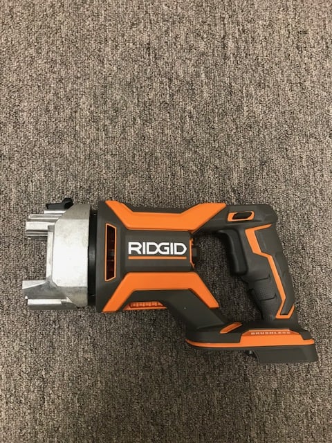
I have a Ridgid MEGAMax Power Base:

Ridgid_yjsyrn.png


I have found a way to make this base power-on without having one of their 3 attachment heads attached (a project in itself!). I will be using it to drive a hydraulic pump. Pump size to be chosen based on Power Base performance. Therefore, I need to know:
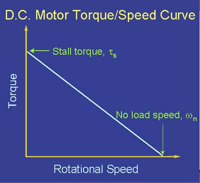
(1) no-load RPM
&
(2a) stall torque or
(2b) torque at some other RPM

From those, I can calculate the RPM at any torque, or the torque at any RPM.

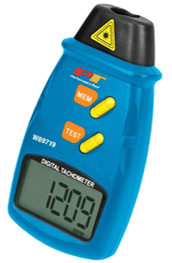
RPM measurement should be pretty straightforward I think. This was recommended:

RPM_Tester_sdqlot.png


My question: What is a simple cheap way to directly measure the torque? I don't want to design a test setup if I don't have to. I did some brief googling but nothing stood out, other than a reply from someone on this forum on another thread, suggesting to measure a base reaction rather than a torque at the shaft. There are no shaft RPM and torque values stated for this Power Base that I could find. There are some values, but they are for the attachment heads, and who knows what kind of gearing takes place inside those. RPM + torque values (together) are extremely difficult to come by on the internet, for any power tool. I have not tried contacting the company. Since it's not the tool's intended use, I'm 100% sure it will be met with disdain. I'm also 100% sure I'll have to correspond with a salesman, and there is only a 25% chance he'll comprehend what I'm looking for. I want to discuss with engineers.

More googling after posting this. Is the answer a "torque transducer"?
 
Replies continue below

Recommended for you

Just get a simple pump and measure how long it takes to pump so many pounds of water up to a certain height, figure your horsepower, then your torque.
 
There are several unknown efficiencies in involved with using energy methods.
 
Thanks to all who responded. Great to hear different ideas of how to go about the task.

I narrowed it down to 3 ideas from the ones you guys gave me: used torque transducer, equal-sided lever with scale, dual-handle dial torque wrench. I discussed them with my boss. Ever the hydraulics guy, he wants to just go ahead and hook up a hydraulic pump similar to one we'll ultimately use for the final product, use our shop testing system to run the testing and collect data, and then calculate RPM and torque.

We will measure free-flow with a flow meter. With this flowrate data, pump displacement, and pump volumetric efficiency (~99% for all pumps at free flow conditions, in my experience), we will calculate the Ridgid's no-load RPM.

We will measure max attainable pressure with a pressure gauge, and we will do so by closing down on a needle valve until there's no flow. With this pressure data, pump displacement, and pump mechanical efficiency (from this pump's curves/data), we will calculate the Ridgid's stall torque.

We will also run and collect data from a couple intermediate operating points in between the 2 extreme points.

This should give us enough data to quantify the Ridgid motor.

We will of course have a relief valve in the test system, with sufficiently rated test system components. We have chosen a pump displacement for this test that we think should keep the pump's max attainable pressure below the relief valve's max capable setting, and below system component ratings.
 

Keith, first, thanks for your detailed and orderly post, and for taking the time to do that. I appreciate it. If I may, can I ask why you think the stalled torque determination is useless? As I understand from researching performance of DC motors, if you know the no-load RPM, and you know the zero-speed stall torque, you can then calculate the RPM at any other torque. Or, you can calculate the torque at any other RPM.

Example:

If by testing or manufacturer's data, say you know the following to be true for a DC motor:

No-load RPM = 1500 RPM
Stall torque = 250 in-lb

If torque during operation = 50 in-lb, then speed has to be:
1500 RPM - (50 in-lb / 250 in-lb) * 1500 RPM = 1200 RPM

If speed during operation = 600 RPM, then torque has to be:
250 in-lb - (600 RPM / 1500 RPM) * 250 in-lb = 150 in-lb
 
You could turn the sample pump into a dynamometer by mounting it to freely rotate on bearings and measure force at reaction arms attached to the pump. Then simple force x lever arm length would calculate torque. Or reverse the mounting scheme for fixed pump and freely rotating mount for the power head.

Ted
 
Get the right angle drill accessory from HD; you can always return it. Hand rotate the input shaft and count rotations for at least two output shaft rotations to get the Gear Ratio Input/Output. Put a spade wood drill bit into drill and clamp bit into a bench vise. Get a digital weight/force scale and attach it to a moment arm onto the drill hand grip. Force x distance (moment arm) will give torque at zero speed. Divide measured torque by gear ratio to get net torque of the MegaMax unit. You could hack up the right angle drill accessory to save the mating housing adapter and the shaft to connect to your pump project. I have one of these scales:


Walt
 
Walt,

I already bought and hacked up the rotary hammer attachment head:

Ridgid_MEGAMax_Power_Base_with_Short_Flange_Piece_Attached_-_Side_View_shbwnw.jpg


Something's amiss with the speeds. By counting turns on the rotary hammer attachment head, the gear ratio is about 11. The Ridgid literature ( says max speed for the rotary hammer attachment head is 1400 RPM. That's got to mean output of the rotary hammer. That would mean the Power Base shaft speed is 1400 x 11 = 15,400 RPM. When I pull the trigger on the Power Base with nothing attached (see pic above) and look at the shaft, it just doesn't seem like anywhere near 15,000 RPM. I took it to a shop guy who's seen a lot more motor and pump shafts spinning than I have, and he guessed 1800 RPM. When I was researching power tool candidates for this project, I didn't see any above 1800 RPM.

So one of 3 things:

1. I'm bad at judging shaft RPM.
2. The published 1400 RPM output number for the rotary hammer attachment head is wrong.
3. With rotary hammer attachment head connected, the Power Base is going to a very high RPM mode in order to get 1400 RPM output. With nothing attached, the Power Base defaults to a much slower RPM.
 
1400 sounds high for a rotary hammer.
But I'll bet that this reads what is attached and adjusts speed (and maybe torque) for each tool.
These motors can be operated in (nearly) constant torque across the speed range, or with some torque curve.

= = = = = = = = = = = = = = = = = = = =
P.E. Metallurgy
 
Ed,

1400 RPM is for the "drilling" mode of the head. The head has 3 modes.

That's not my understanding of how DC motors work. Torque is 0 at max RPM, and increases linearly to its maximum ("stall torque") at 0 RPM. As torque goes up, RPM goes down.

colorTS1_mig1ap.jpg
 
If you drive at constant voltage.
Are they controlling voltage or current? is this speed control or torque control?

= = = = = = = = = = = = = = = = = = = =
P.E. Metallurgy
 
The Power Base is battery powered (18V, 9 Amp-hr), so voltage should be constant at ~18V.
 
The voltage to the controller is 18V, who knows what it is to the motor.
The other thing is that even if they are are in voltage control and your torque curve is right we don't know what part of that range we have access to. I am sure that the controls limit us to a portion of that curve, maybe even shifting control methodology based on the tool and/or speed/load.

= = = = = = = = = = = = = = = = = = = =
P.E. Metallurgy
 
There is most likely a planetary gear set in the housing between the motor shaft and the output shaft that appears as the power base output drive.

Ted
 
I agree with both EdSS and hydtools. Your theory is basically correct for a naked motor but there are too many unknowns for those end points to be useful. Starting with this being a brush-less DC motor which actually means it's a 3-phase AC motor with electronic commutation. I wouldn't trust those endpoints for calculating a door-stop. You want empirical data for your empirical application.

Keith Cress
kcress -
 
HydraulicsGuy:
Why not take a 48” beam (some length) of some sort, maybe a .5” x 2” stl. bar. This all depends on the approx. strength of your powerhead motor. You need a load attachment means at one end of the beam, and 48” away, you need a rigid torque attachment/transmitting feature for your powerhead motor. One the center line of that torque attachment feature, you need a knife edged pivot below the bot. edge of the beam, maybe in a small detent groove on that edge, or maybe a couple ball type roller bearings on the same axis as the torque attachment feature. Over the load attachment, and allowing only 6 or 8” of beam tip upward rotation, provide some sort of a stop to prevent things from going crazy. Then, apply the torque slowly, or start with a weight you know you can’t lift, and start removing weight. Of course, you have to add the weight of the beam at its c.g. into the hold down torque.
 
The test that we will end up doing with an actual hydraulic pump, as I described way above, should give us sufficient data on the motor.

So what do you all think the actual motor curve looks like, if you don't think it's a line (or approximately a line) like I posted above?
 
dhengr, I was trying to stay away from designing any kind of test setup. Either way, my boss has decided on a test with a hydraulic pump (see my post above 26 Feb 20 14:21).
 
This might make your idea interesting - from the website - "Smart Power Base automatically identifies the attachment head (not included) and configures settings to match; "

So how are you going to get the power base to do what you want it to?

Fro a user review - "This Base is intuitive and sets torque and RPM, based on which head is attached."

Hmmmm. Maybe you will need to use one of the heads and attach it to the pump....

Remember - More details = better answers
Also: If you get a response it's polite to respond to it.
 
For a brushless motor I don't think you'll find any curves for the motor alone. The controller is intimately mated to the motor as far as performance is involved. You can't drive a brushless motor with a constant DC current. The controller puts out pulses to the field coils. The field "rotates" in the motor. The speed of the rotation is proportional to the speed of the motor. I believe the primary limitations to speed and power and torque would be the inductance of the motor and/or the ability of the controller to turn on and off the pulses quickly.
 
Status
Not open for further replies.

Part and Inventory Search

Sponsor