4pole motor. 1400rpm @ 46.7Hz @ 3,300V.
ok then the supply frequency to obtain 500rpm = 8.33hz would be 46.7*(500/1400) = 4*500/120 = 16.7hz
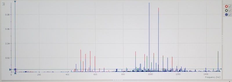
The 2*LF spacing would be 33.3hz. It looks like 33hz is the spacing betwen some of the peaks between 400 and 600hz and again between 1000 and 1200.
If I had to guess your rotor bar frequency may be around 500hz which would correspond to 500/8.33 ~ 60 rotor bars. So it may be you have a familiar of RBPF+/- k*2LF and another family at 2*RBPF +/-k*2LF. There are some additional peaks in there that may not be fully explained by the pattern but that pattern is fairly benign in my opinion (please ignore any chart which tells you that indicates rotor problem... in some cases rotor problem can be accompanied by increasing rbpf pattern but the pattern also exists in healthy-rotor motors and can vary over time for a variety of reasons unrelated to rotor condition.).
What is an acceleration TWF? I am not familiar with the term.
Sorry, TWF stands for Time Waveform. It is a plot of acceleration samples vs time. From that one might be able to deduce true peak acceleration (although true peak can be missed if sample rate is not high enough) and whether the vibration is stable over time. The TWF may also give other clues... impacting has a distinctive appearance with sharp peaks and possible ringdowns, whereas electrical/rbpf-pattern vibration tends to be smoother (at least on non-vfd motors).
So the sensors on these motors are vibration sensors reading in in/sec from 3-1000Hz. The manufacturer recommended trip setting is 0.15in/sec RMS (which I also thought sounded low, but when it's vibrating at 0.20 in/sec for 5 seconds before it shuts down, you can really feel it in the floor)
The in/sec sensors were only being logged at 10Hz data rate so pretty much useless for FFT. As of today, they were logged at 5,120Hz but I have not had a chance to analyze the data and create the FFT plots yet.
If your setpoint is in ips and you are trying to troubleshoot the reason for the trip then
you should be looking at a spectrum in velocity units (not in acceleration units) [EDIT - I apologize for not reading closer, it appears you knew that, and are already working your way in that direction]. That will give you a better idea of what is contributing to the trip assuming the trip is based on an rms of the velocity which I think is typical (true peak is traditionally reserved for acceleration). I think trying to analyse the high frequency stuff visible in acceleration is not very productive in this case, as in most cases... it tends to be harder to interpret and carries less diagnostic value (other than maybe for rolling element impacting or gear diagnosis)
If 33hz is a big contributor to velocity, that's 2*LF electrical, usually not much can be improved there (maybe check airgap and voltage balance).
If 1x is a big contributor to your velocity then maybe balancing would be in order.
I would also question why the trip needs to be so low (0.15ips). That is not a typical trip level for a motor unless there is sensitive equipment driven or nearby
Vibration felt on your feet may be a characteristic of the support structure floor. Also if you are comparing to other machines I'd say you will feel 0.15ips at 500cpm a lot more than you will feel 0.15ips at 3000cpm (our touch is more sensitive to the lower frequency). Either way, if you want to better understand the significance of the floor vibration then try to determine the frequency of the floor vibration.