Continue to Site

Eng-Tips is the largest engineering community on the Internet

Intelligent Work Forums for Engineering Professionals

  • Congratulations Ron247 on being selected by the Eng-Tips community for having the most helpful posts in the forums last week. Way to Go!

Force Sensing Resistor placement

Status
Not open for further replies.

Menessis

Mechanical
Oct 26, 2012
6
Need some help getting my head around what I need to build to make this work. If you look at the links I have listed here you can see a drawing of what it is that I am talking about. I want to put a FSR at the 4 cardinal positions in this joystick. I would like it to be bolted up tight so nothing moves. So when I push the stick forward the forward FSR in conjunction with the rear FSR will out put the amount of force applied. My question is will the FSR be able to "read" anything in this configuration? The second concern is will the left and right FSR's values change while pushing forward.

Post 415 shows a pic of the model

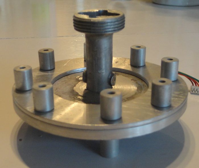
Post 433 shows a pic of the plates and the spacers that will be used to hold in the base.

Maybe I should give up on the FSR's and go with the mini strain gauge. But then I have to work out the electronics end of things.

Any thoughts?

Thanks
Menessis
 
Replies continue below

Recommended for you

Member only forum....didn't see that one coming.

OK this is what I have so far. The tubes on top are the eight spacers that the bolts pass through to hold it in place. The tubes on the bottom are not part of the project. The FSR's will be in 4 locations. Top, bottom, left and right between the two discs.

CougarMod_01_zpse9e02b7e.jpg


Thanks for letting me know about the dud links Scott.

Menessis
 
Could you use a miniature version of a mechanical torque wrench inside the joystick stem? Hollow pipe with solid rod in the center, rod is mounted to the top of the joystick handle only.

Excessive force will deflect the rod towards the pipe on the bottom end of the joystick. Use location of this rod to read force. (In a torque wrench, the rod would deflect and indicate on a scale, the tq applied.)

Have you identified the FSR you will be using? It wasn't clear between unusable links and lack of info in original post, this suggestion may or may not work with what you have in mind. But, in any event there may be some merit to moving the force reading away from the mounting bolts.

If you want to simplify components, consider some type of pneumatic or hydraulic bladder system to push pistons tied to linear actuators. This could transform small deflections in mounting plates to useable linear positions. Placing the bladders should be pretty intuitive, sandwich between two mounting plates, one of which has at least a small amount of flexibility. Now I think I like this suggestion more than the first, but I've already typed it so I will leave both.
 
Presumably, these resistors technically measure strain, i.e., deformation of its mounting substrate changes the FSR resistance. I don't see how putting them on a metal substrate will get what you want, unless the forces are gigantic.

TTFN
faq731-376
7ofakss
 
The joystick handle goes on the threaded portion. There is a wire harness inside also. I have a set of FSR 402.

Menessis
 
Force Sensing Resistors are neither accurate nor precise. So if you want to know how much force is applied they are not a good choice.

Four of any type of sensor is over-constrained and makes the math harder.

Use three strain gauges on the tube, 120 degrees apart.
 
Some one on another forum has worked out the electronics to wire a pair of FSR's together to act like a trim pot. By doing it that way it just plugs back into our boards too. And there is an op amp involved as well as trim pots and then last but not least software that we can fine tune it.

Menessis

 
I'm here looking for some guidance in the mechanical end of things.

Menessis
 
In answer to the OP, FSRs MIGHT work if there is sufficient deflection of the plate, and if there is, then the cross axis FSRs will indicate something.

TTFN
faq731-376
7ofakss
 
Should you be using force as your measuring means, or relative displacement to some solid stop point as the measuring means at the three or four points? Which is the easier to deal with in terms of the math, mechanics, wiring, and computer software, etc. If you use force on the joy stick to get the machine to act faster, stronger, whatever; I wonder if the operator’s temptation isn’t to break the joy stick off trying to make things happen faster, stronger, etc. How do the joy sticks on a Caterpillar backhoe work?
 
@IRstuff That's what I thought too. The software will allow me to put a dead zone in and that may deal with the cross axis as you put it. I only get 20 to 30 ohms difference so I guess I have to just try it and see.

Menessis
 
Status
Not open for further replies.

Part and Inventory Search

Sponsor