Continue to Site

Eng-Tips is the largest engineering community on the Internet

Intelligent Work Forums for Engineering Professionals

  • Congratulations cowski on being selected by the Eng-Tips community for having the most helpful posts in the forums last week. Way to Go!

Force required to lift one end of infinitely long beam 1

Status
Not open for further replies.

tomecki

Mechanical
Aug 18, 2014
18
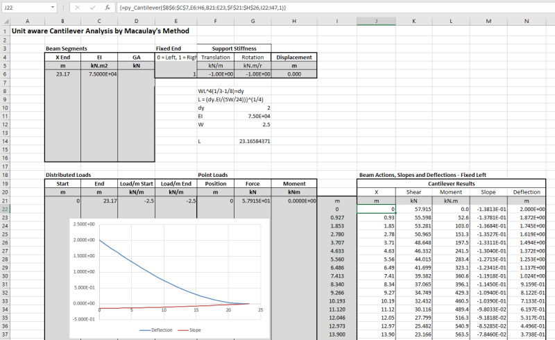
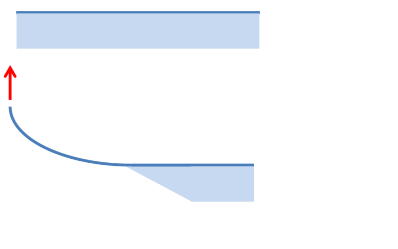
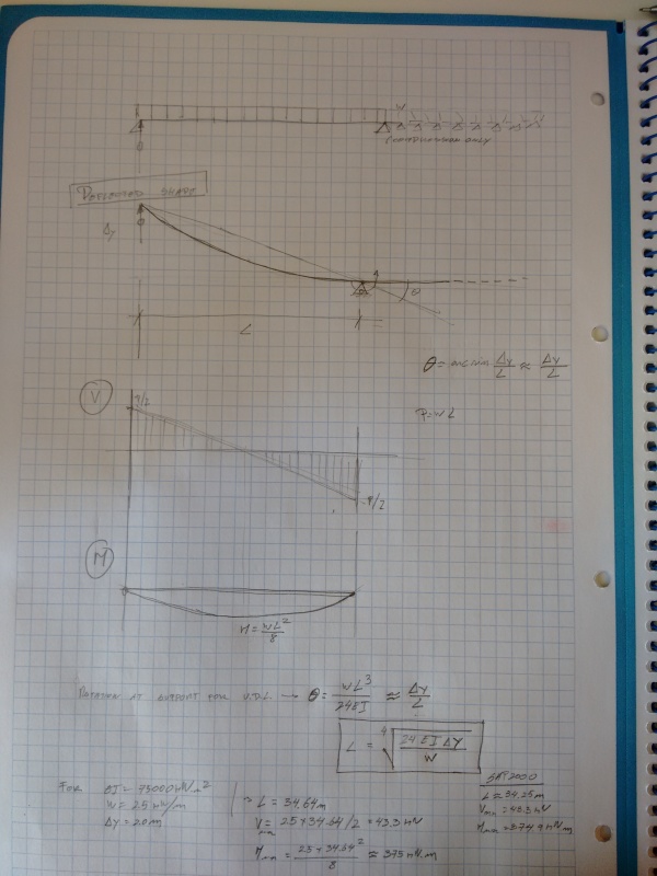
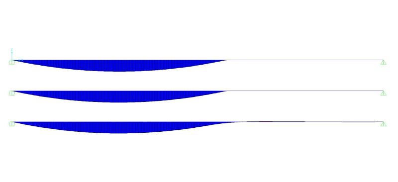
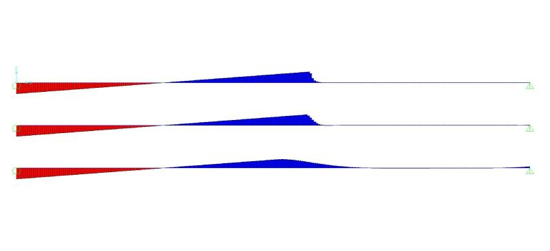
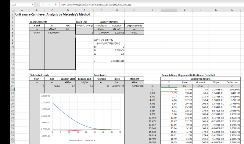
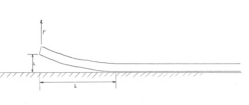
I'm trying to figure out the force required to lift up one end of a long pipe by 2m. The pipe is long enough that the entire length of it will not lift off the ground. It will bend under it's own weight and become tangent with the ground at some unknown point away from the end.

I tried to model this using various beam formulas but I end up with two unknowns (the force on one end and the length that lifts off) and can't solve them.


Pipe_lift_bsewhp.jpg
 
Replies continue below

Recommended for you

I thought Denial had beaten me to it, but I don't think his analysis is quite right.

Again assuming infinitely stiff support, the lifted part of the pipe can be considered as a cantilever with a point upward load at one end, an equal downward distributed force, and a point moment at the other end. The end deflection is therefore WL^4/3EI - WL^4/8EI, which gives the L required for an upward deflection dy as:

L = (dy.EI/(5W/24)))^(1/4)

Using guessed values for a concrete pipe of 0.5 m diameter of w= = 2.5 kN/m, EI = 75,000 kN.m2 and dy = 2m I get L = 23.166 m, which if I feed it into my cantilever spreadsheet gives me exactly 2 m deflection:

Pipe-def_asfj3p.png


The end moment is about 670 kNm, which would be way over the bending capacity of an RC pipe of 500 mm diameter.

Also note that this assumes uniform stiffness. A segmented pipe with joints that allowed partial hinging would obviously allow a much shorter length, and reduced moment.


Doug Jenkins
Interactive Design Services
 
IDS ...
"the lifted part of the pipe can be considered as a cantilever" ... ok,
"with a point upward load at one end," ... again ok, the force F, but
"... an equal downward distributed force" ... no (unless equal means uniform, which I don't think you meant from your equations); the distributed load is the weight of the pipe, not the force at the tip.

another day in paradise, or is paradise one day closer ?
 
No, Denial, it's a cantilever, not ss. Look at the boundary conditions at the point of lift off. Deflection=0, gradient = 0. It is a cantilever encastre at the point of lift off. The analytical condition is a sum of two cases, F upwards, and a distributed load of mg/l downwards.

That ignores ground stiffness, shear effects etc.


Cheers

Greg Locock


New here? Try reading these, they might help FAQ731-376
 
rb1957 said:
IDS ...
"the lifted part of the pipe can be considered as a cantilever" ... ok,
"with a point upward load at one end," ... again ok, the force F, but
"... an equal downward distributed force" ... no (unless equal means uniform, which I don't think you meant from your equations); the distributed load is the weight of the pipe, not the force at the tip.

Equal means equal in value to the end force. At the point of contact with the ground the shear force must be zero; if it wasn't the pipe would lift some more length of the ground, so the end upward force must be equal to the weight of pipe not in contact with the ground. The equations are the end deflection for a cantilever with an upward force W, and a cantilever with the same force W uniformly distributed over the length, downwards.

GregLocock said:
That ignores ground stiffness, shear effects etc.

It assumes infinite ground stiffness, so it's an upper bound on the length. Shear effects with a pipe over that length are negligible. Variation in the pipe flexural stiffness would have a far bigger effect, but with a pipe of about 0.5 m diameter the only wayit is going to work without excessive bending moment is if the pipe joints allow sufficient rotation to get the required curvature without excessive bending.

Doug Jenkins
Interactive Design Services
 
I think the lower bound for the lift force is 1/2 the weight, in this case the lifted portion is like a SS beam with zero end moment and 1/2 the weight supported at the ground end.

I think the end moment opposes the lift, so the lift force will be higher than 1/2 the weight.

The upper bound of the lift force ... I don't think there is one !? if the lift equals the weight, then there's no shear reaction at the ground contact point, only a fixed end moment (= WL/2). if the lift exceeds the weight then there's a down reaction against the ground and a higher fixed end moment (= WL/2 + (F-W)L).

another day in paradise, or is paradise one day closer ?
 
I'm not convinced... if you add more force and lift the end higher, the point of tangency just moves to the right...

Dik
 
IDS has it. That's exactly how I was envisioning the calculations and the reasoning behind it. You can't ignore the stiffness of the pipe as suggested by others, this problem is mostly governed by the stiffness of the pipe.
 
jayrod:

Maybe mostly governed by the height you lift the end...

Dik
 
"At the point of contact with the ground the shear force must be zero; if it wasn't the pipe would lift some more"

no, I think it's not unreasonable that the shear at the ground contact is down (into the ground).

by balancing the weight of the lifted portion, then in the ground supported portion the weight is the ground contact force (UDL).
how does the ground supported portion of the pipe react the fixed end moment ?

If F > W, I see the reaction to the fixed end moment locally reducing the ground reaction DL.

another day in paradise, or is paradise one day closer ?
 
I would tend to agree that the shear force must be zero right at the point the pipe starts contact with the ground. Obviously even an inch or two back from that point there would be load supported by the ground.

The amount you lift the end has a direct correlation to the stiffness and weight of the pipe.
 
to me it seems reasonable that the ground contact force is reduced near the lift-off point, rather than seeing a step change in ground contact pressure. something like ...

Untitled_voxent.png


another day in paradise, or is paradise one day closer ?
 
I see this structural system as following:
- Simply supported beam with span L.
- The Dy=2.0m vertical displacement in one end causes a rigid body rotation of the beam of value arcsin(Dy/L)=Dy/L;
- The pipe is loaded with a load w that causes a rotation at the end supports of wL^3/(24EI).
In order that the rotation of this point in contact with the ground is null, wL^3/(24EI)=Dy/L --> L=(24EIDy/w)^(0.25)
The internal forces are caused only by the beam self weight, so Vmax=wL/2 and Mmax=wl^2/8

For the data that IDS provided:
- EI=75000kNm2
- w=2.5kN/m
- Dy=2.0m
we should have L=34.64m; Vmax=43.3kN; Mmax=375kNm

For validation, I plugged this data into a SAP2000 model with compression only springs and the results are spot on for an end displacement of 2.0m.
I enclose a sketch of my calculations (sorry for the poor quality...).
Pipe_Sketch_nknz52.jpg
 
this approach drives the lift force to be 1/2 the weight of the pipe, and zero moment at the ground contact point. I don't see that this is the only solution to the problem.

I think there's some point to the right of the contact that defines the affected part of the pipe; there'd be no shear force or moment on this section, similar to the pipe to the right of this point, the weight is continuously supported by the ground.

Untitled_pdbdq9.png


another day in paradise, or is paradise one day closer ?
 
You're right. There's a small transition zone that depends on the relative stiffness of the ground and pipe. My SAP200 model was done with almost infinite spring stiffness so the extent of this area is quite limited. However, for practical purposes, I don't this as an issue.
I've run a couple of tests in SAP2000 with different compression spring stiffnesses (1E12, 1E6 and 1E3 kN/m/m) to see its influence on bending moments and shear. There wasn't a difference between maximum bending moments and shear forces greater than 0.5%. The difference lies entirely on the extent of the transitiion zone only. I've attached a couple of images showing bending moment and shear diagrams.

Bending moments:
Bending_moments_bqbo50.jpg


Shear forces:
Shear_vl65uh.jpg
 
Apologies to Denial. He had it right.

For an infinitely stiff support, the curvature at the point of lift off will be zero, so the moment is zero and the pipe weight is distributed evenly to either end. With the corrected loads the pipe length required to be lifted is L = (dy.EI/(W/24)))^(1/4), and the lifting force is 34.64 kN (as found by avscorreia).

For a finite support stiffness, the lifting force and maximum moment are reduced, but not by very much. I get the following numbers from a Strand7 analysis:

Support Stiffness(kN/m/m) Lifting Force(kN) Max Moment(kNm)
100,000,000 42.8 371
10,000 42.5 371
100 37.3 290

Revised spreadsheet analysis, with the lifting force set to half the lifted pipe weight:

Pipe-def2_zaszin.png


Doug Jenkins
Interactive Design Services
 
Thanks, IDS.[ ] I was half way through a convoluted attempt to convince you, rb1957 and GregLocock that the suspended portion of the beam is simply supported rather than cantilevered, and you have saved me from it.[ ] I agree with your revised formula for L, provided you correct it for your unbalanced brackets:[ ] it can be derived very easily from my result above.
 
GregLocock said:
I'm going to have to wrap my head around that one, no BM at the point of contact with the ground?

Bending Moment -> 0 as support stiffness -> infinity

But for realistic support stiffness values the lifting force changes very little.

Doug Jenkins
Interactive Design Services
 
Greg.[ ] How about this argument?

Let x be measured along the beam and y be transverse to the beam.[ ] Locate the origin at the point of contact/liftoff, with the resting part of the beam at x>=0.[ ] Simple beam bending theory gives us that M/(EI)=y'' and V/(EI)=y''', where each successive[ ]' denotes differentiation with respect to x.

Let x approach zero from the positive side:[ ] the value of y is zero for all x>=0, so |y''|x=0+ is zero.
Now let x approach zero from the negative side.[ ] If there is a bending moment there, then |y''|x=0- must be non-zero.
Therefore at x=0 y'' must undergo a step change, Heaviside function style.[ ] In simple beam theory this cannot be achieved except by a concentrated applied moment.[ ] There is no possible mechanism by which a concentrated applied moment could be generated in the simplified structure under consideration.[ ] Therefore the bending moment at both x=0- and x=0+ must be zero.

Quod erat demonstrandum.
 
Status
Not open for further replies.

Part and Inventory Search

Sponsor