Hi All, I would appreciate your thoughts and feedback on a cranked beam support over a masonry wall.
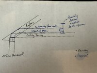
I'm designing a cracked beam to support a new suspended floor inside an existing roof. To avoid damaging the ceiling below and to maintain the lateral stability of the roof, we will need to keep the ceiling joists. Due to its height in relation to the existing masonry wall, the cranked beam seems the only solution in this case. See photos with the scheme and the assumed support diagram.
Now, I have a transverse beam that would provide lateral and vertical supports for the new cranked beam. The beam is embedded in the external walls.
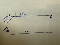
By designing the cranked beam as a roller support, I have a small horizontal deflection of more or less 1mm in the cranked beam. I may be overthinking this, but just wondering about the cranked beam triggering friction against the wall and the overall stability and the reality of a roller in that case.
I can not have a pin there due to the lateral stability of the wall and the high thrust/axial load that is going to trigger on the cranked beam.
Thank you for your thoughts and views on this.
I'm designing a cracked beam to support a new suspended floor inside an existing roof. To avoid damaging the ceiling below and to maintain the lateral stability of the roof, we will need to keep the ceiling joists. Due to its height in relation to the existing masonry wall, the cranked beam seems the only solution in this case. See photos with the scheme and the assumed support diagram.
Now, I have a transverse beam that would provide lateral and vertical supports for the new cranked beam. The beam is embedded in the external walls.
By designing the cranked beam as a roller support, I have a small horizontal deflection of more or less 1mm in the cranked beam. I may be overthinking this, but just wondering about the cranked beam triggering friction against the wall and the overall stability and the reality of a roller in that case.
I can not have a pin there due to the lateral stability of the wall and the high thrust/axial load that is going to trigger on the cranked beam.
Thank you for your thoughts and views on this.