Continue to Site

Eng-Tips is the largest engineering community on the Internet

Intelligent Work Forums for Engineering Professionals

  • Congratulations waross on being selected by the Eng-Tips community for having the most helpful posts in the forums last week. Way to Go!

Field Retrofit of Steel Beam Connection

Status
Not open for further replies.

jdgengineer

Structural
Dec 1, 2011
748
We have a field condition which we'll need to retrofit for a connection between a steel beam and supporting girder. The steel fabricator erected all of the steel before sending us shop drawings for review (we have told them this is not acceptable). As a result, we have an odd condition where the TOS for the beam is ~2 1/2" above the TOS for the girder. Had we reviewed the shop drawings we would have raised the TOS of the steel of the girder and avoided this condition.

IMG_20161222_104021_xwdkos.jpg


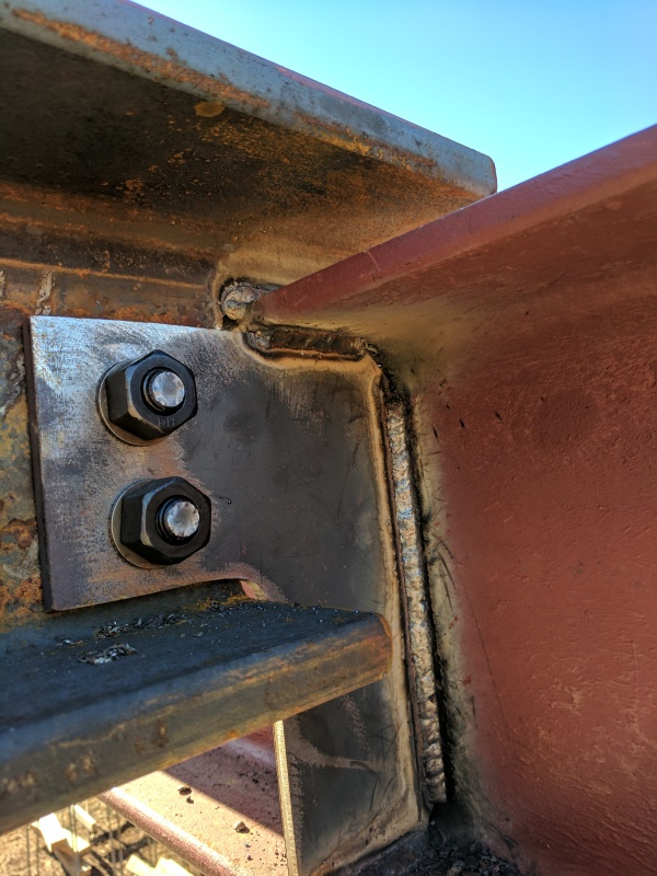
The beam is a W8x67 and the girder is a W12x50 (don't ask -- residential construction). To make the connection the steel fabricator notched the W8x beam and welded the web of the beam to the top of the girder. They then installed a notched extended shear tab with (2)-3/4" A325N bolts to the web of the W8x beam. The loads are not extreme (~12k LRFD)

Now that the condition is constructed we are left trying to accept the connection or find a field fix. In my opinion there are currently two load paths:

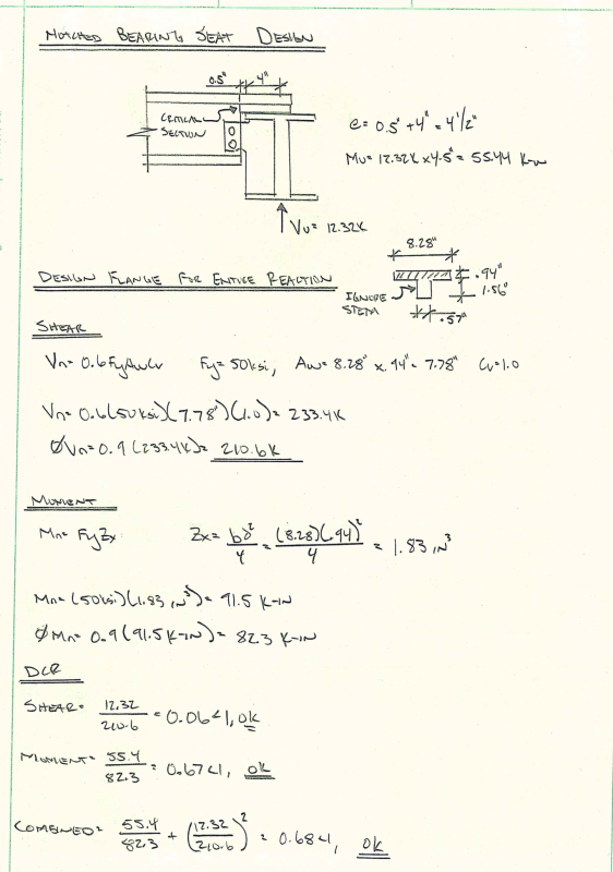
1) Notched bearing seat
2) Extended shear tab

Due to unknown potential differences in stiffness I want to resolve the connection solely with one of these two load paths (i.e. not combining two). The notched bearing seat almost calcs outs (works for shear but fails in flexure if we assume the reaction point is at the web of the W12x to avoid introducing torsion into the beam). It fails by ~5% so it's pretty close. However, the notch is pretty extreme and almost the entire web is cut out. Even if it calced out I'm not sure how comfortable I would be with it.

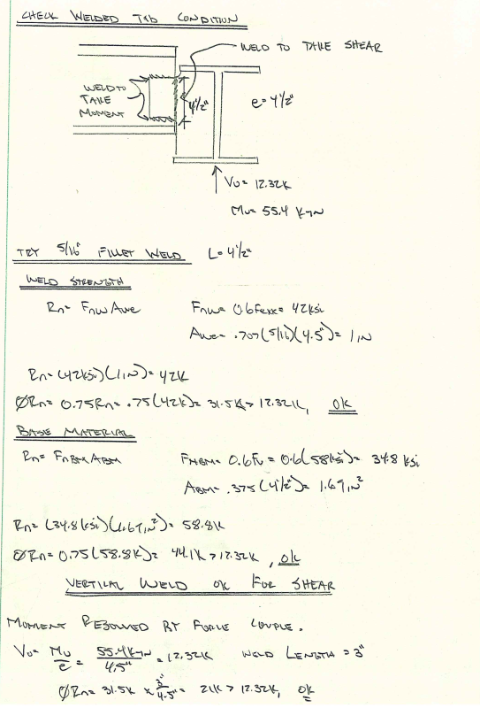
Therefore, I'm left trying to get this to work through the extended shear tab. With the notched bearing seat I believe we have lost the rotational ductility of the connection and it should be considered "fixed" now. However, due to the fact it is a single-sided connection introducing torsion into the girder I don't believe the moments would be significant as a result. Therefore, I'm not overly considered about the rotational ductility of the connection as I believe the adjacent girder will provide an essentially "pinned" reaction.

Counting only the extended shear tab RISA Connection says the connection fails with DCR = 3.2. This failure is due to plate flexural failure as well as eccentric bolt failure.

As a fix, I can think of three potential options

1) Weld the backside of the shear tab to the web of the beam. This significantly reduces the eccentricity
of the connection. However, the line weld is not capable of resolving the torsion on it's own. I could then also weld the other 3 sides of the shear tab to provide better torsional resistance. However, in order to avoid plate flexural failure I'd need to assume the vertical force is resolved by the inside weld and the other 3 welds only provide moment resistance. Considering the difference in stiffness between the beam and the shear tab I think it could make sense, but I'm not sure how comfortable I am with this approach. This would be the easiest fix though. Normally, I know welding shear tabs is a bad idea, but due to the inherent flexibility of the supporting girder in torsion it seems to me to be acceptable in this instance.

2) Provide another shear tab on the other side of the web. In order to get the flexural strength of the plate to calc out, this plate would need to be 7/8" thick. The 3/8" plate and 7/8" plate would be able to act in unison and the bolts would be in "double-shear" (sorta). I would design each plate to take the load based on their stiffness (i.e. thickness of plate) and check the bolt reaction based on this stiffness assumption (therefore not truly double shear). The 2nd shear tab would then be PJP welded to the web of the girder / flanges on 3 sides. The bolts would need to be swapped out with longer A490X bolts.

3) Similar to #2 but abandon the bolts and weld web to shear tab.

I'm leaning towards Option #2. Any thoughts?
 
Replies continue below

Recommended for you

One of my favorite responses to these situations where some unconventional approach is implemented without first getting it reviewed is to suggest load testing. Load test to max anticipated service load and do some dye penetrant testing, visual inspection, and measurements afterward.

You could give the fabricator a choice between one of your options and load testing. The reasoning behind this is to nullify that situation where you're made out to be the villain regardless of outcome. If you force a repair then they could claim that it wasn't necessary, but if you give them the choice you can be honest when you shrug and say, "it may be adequate but there's no precedent for this so I really don't know".
 
Would it work if you assumed all of the moment and shear went into the beefy flange of the supported beam? Ignore the stem contribution altogether?

Another fix option might be to weld a seat angle on to the girder web stiffener. Take a good look at weld access though.

I like to debate structural engineering theory -- a lot. If I challenge you on something, know that I'm doing so because I respect your opinion enough to either change it or adopt it.
 
Hi KootK. I checked it with the stem and it didn't work so I wouldn't think the flange only would work. I'm conservatively assuming the moment arm to be distance from center of girder to notch in beam. If I shortened this moment arm length (induce small torsion into girder) it would probably work.

Wouldn't the beam seat induce torsion into supporting girder?

What do you think of my other retrofit options?
 
And thanks theonlynamenottaken for the load testing idea. I haven't done this before. I believe 2012 IBC (permitting code) wants 2x service loads and 2015 IBC (code effective 2017) wants 1.0 x strength design loads (although I don't have in front of me). I could look into this more closely but would prefer a pencil / paper approach for now. $$$ for field fix (short of replacing beam) shouldn't be too big of a deal and good lesson for fabricator.
 
With regard to using the flange alone versus the tee section, I thought there might be something to be gained if it was the difference between a Zx analysis with the former and an Sb analysis with the latter. But, if you say it ain't so, I'll take you at your word.

The beam seat would deliver shear eccentrically to the girder so yes, in that respect you would have torsion in the girder. I see that as a non-issue however as what you currently have out there already constitutes a moment/torsion connection between members in my opinion. So it's just compatibility torsion.

I think that either of your options could be made to have sufficient capacity. They just both strike me as a lot of work to deal with what seems to be pretty minor load. Option two seems especially laborious and, perhaps, inpesction intensive.

I like to debate structural engineering theory -- a lot. If I challenge you on something, know that I'm doing so because I respect your opinion enough to either change it or adopt it.
 
I don't have a solution, but here are a couple thoughts:

When RISA checks the shear tab in bending, does it consider the full depth portion with maximum moment at the notch (Mu=12k x ~1.5"). Or, does it assume it is simple shear tab welded only to the W12 web (maybe 3" high x 6" long with Mu = 12k x ~4.5").

If the shear tab is A36, any chance the contractor has mill certs? The plate may be closer to 50ksi yield.

What is eccentric bolt failure? Is the bolt failing in shear. Or is the shear tab failing in bearing or rupture?
 
Your extended plate here is a good deal more stable than is the AISC manual case. My inclination would be to:

1) Check shear on plate section.

2) Assume the plate cantilevers from the girder and check My on the plate at the edge of the web stiffener.

3) evaluate the stiffener for compression buckling at the same location as #2.

4) if number 3 doesn't work, add reinforcement to force it to work.

My money says this makes for a do nothing solution and actually preserves considerable rotational ductility.


I like to debate structural engineering theory -- a lot. If I challenge you on something, know that I'm doing so because I respect your opinion enough to either change it or adopt it.
 
For what it is worth, they are nice looking welds.
 
Regarding your repair options:

jd said:
1) Weld the backside of the shear tab to the web of the beam. This significantly reduces the eccentricity
of the connection. However, the line weld is not capable of resolving the torsion on it's own.

If you need to combine welds with bolts I'd avoid this; too much of a hassle in my mind. Get it so either the bolts or welds can take it alone.

jd said:
2) Provide another shear tab on the other side of the web.

This sounds needlessly expensive with the PJP welds. I see nothing wrong with your second plate having fillet welds on only one side and it will be a much cheaper connection.

jd said:
3) Similar to #2 but abandon the bolts and weld web to shear tab.

Nothing wrong with this; you're already field welding there so adding a bit more welding will make little difference. Make sure you check that you have enough material in the web of the beam for all the fillet welds.

Professional Engineer (ME, NH, MA) Structural Engineer (IL)
American Concrete Industries
 
I would probably add a 2nd gusset pl on the other side with fillet welds....only question in my mind is would a one-sided fillet weld be ok?...I can not see, at the momnent, any problem with it....another approach might be extending and reinforcing the top fla of the W8 so that it bears on the the top fla of the girder and then checking the extended fla(reinforced) for shear and bending while ignoring any contribution of the installed conn...
 
SAIL3 said:
only question in my mind is would a one-sided fillet weld be ok?

With the other plate with presumably double-sided fillet welds I would suspect it is acceptable. Plus, I doubt you could get the welds to rotate enough to break them as the plate is being bent in-plane for the most part and the welds to the flanges and web of the girder would limit how much that plate can bend out of plane.

Professional Engineer (ME, NH, MA) Structural Engineer (IL)
American Concrete Industries
 
>>>The beam is a W8x67 and the girder is a W12x50 (don't ask -- residential construction).<<<

You said don't ask but may I anyway? Were they selected to accommodate limited clearance or are they doing double-duty as lateral drag structs or somehow otherwise taking compressive force as well as bending?

The reason I ask is I once saw some similar size members used in residential construction where clearance was not an issue and I could never figure out why they were selected. I finally concluded that perhaps the designer didn't realize the beam was fully braced and therefore designed for the full length being unbraced. But I wasn't fully privy to all the lateral load paths so I'll concede they may have been designed for combined bending and compression.
 
Thanks, as always for all the input. You all are making me rethink the condition a bit. Sounds like in general most of you are more comfortable with the connection then I was at first glance.

Kootk -- I took a closer look at the notched bearing seat using only the top flange. It looks like it may calc out. See below. Do you agree in general with the approach? I combined the stresses per H3-6 of AISC 360-10. This isn't technically required as I don't have torsion, but as the flange is in both max shear and moment at the same time it seemed appropriate. In reality the shear demand is quite low that it doesn't really matter.

Bearing_Seat_zngmid.png

I'm not sure I agree with the idea that it is just compatibility torsion. It seems due to the eccentricity of the shear force the torsion is required for stability. I understand compatibility torsion for concrete spandrel beam that has alternate ways to shed the load, but here it seems the eccentricity needs to be resolved by one path or the other. The girder in torsion seems to be inappropriate to me as the beam is just resting on small tube steel columns which don't seem to provide very much torsional restraint.

I don't love the idea of a single-sided fillet connection. I've always been taught to avoid in all situations. I was under the impression that just the small eccentricity caused by the fact that the weld is outside of the plate is enough to potentially cause undesirable weld stresses. If I'm going to weld a new plate I think I will use PJP. The other plate does have a double-sided fillet.

For the extended shear tab I've assumed all eccentricity is resolved in the supported beam (i.e. through the bolts) and generally followed design procedure of 10-104 of AISC 14th Edition. RISA Connection I believe follows this procedure as well. If the eccentricity is assumed to be resolved by the bolts, it seems to me that the maximum plate moment occurs at the notched section and not the full-depth section. Therefore, to model in RISA Connection I've assumed the plate height is only the height of the notched section. The girder weld check is not accurate as we have 3-sided weld, but I think other checks are appropriate with the condition.

Extended_Shear_gpjpx0.png


As the notched bearing seat seems to calc out I'm starting to feel more comfortable with the "do nothing" approach. Although, I think I would still at the least like to weld the shear tab to the beam to reduce the eccentricity. Due to the flexibility of the girder rotation I think I'm ok with the welded shear tab connection even though they are generally not recommended due to rotational ductility concerns (and welded bearing seat already threw that out the window).
 
Archie -- The W8x67 beam was sized to fit within LVL 1 3/4 x 7 1/4 floor framing. There is a 2 1/2" overbuild above the floor framing and the top of the beam will eat into that space a bit. The W12x beam is over a window and did not have the same dimensional limitations. The offset is due to the fact that the W12x beam was set at bottom of floor plywood rather than into overbuild like the W8x beam. TOS elevations for residential construction are not often specified on structural drawings and are usually resolved during shop drawing review (not ideal practice I know).
 
So in this case it was to accommodate dimensional constraints. Gotcha. Thanks for info.
 
Below is a quick and dirty calc for the welded shear tab. This assumes that the vertical weld on the inside of the plate takes all of the shear and the horizontal welds are only there for moment resistance. As the beam is much stiffer than the plate it seems that this load distribution might make sense. Not completely convinced, but considering it.

With this load distribution, it looks like things work out. The eccentricity is coincidentally 4 1/2" in both directions.

Welded_tab_zs4qmj.png


I'm starting to lean towards my Option #1 solution which would involved welding the tab as calced above. Considering it technically calcs out with the notched seat it seems like this added reinforcement may not be needed but would make me feel a bit better about the connection.

Any other thoughts?
 
Your flange check works for me. I might have multiplied the shear stress by 1.5 (debatable) and gone with a Von Mises interaction check but, based on your numbers, that would be just splitting hairs here. And, personally, with the flange check working, I would be happy to simply leave it at that.

In this situation, there is but one requirement for your torsion to be of the compatibility variety: beam end rotation should match girder twist at the point of connection. And I would argue that requirement is met in spades here.

Why are you proposing to weld the one vertical interface and two horizontal interfaces of the existing plate for your option one? Would it not be easier and more effective to weld the two vertical interfaces instead?

I have some issues with treating this as an extended shear tab connection:

1) oddly, the presence of the full depth stiffener can reduce capacity and disregarding it can be non-consevative.

2) assuming moment in the bolt group strikes me as unrealistic. Here, you'll have axial tension in the top flange connection and axial compression plus shear in the bolt group. As you mentioned though, who really knows where the shear goes. I'd guess predominantly through the top flange connection.

If you're bound and determined to make the plate work on it's own, I really feel that the four step evaluation procedure that I mentioned previously is a better way to go.


I like to debate structural engineering theory -- a lot. If I challenge you on something, know that I'm doing so because I respect your opinion enough to either change it or adopt it.
 
if one finally decides to go with the extended bm fla bearing on the top fla of the girder, I would reinforce the extended fla to make it as stiff as possible or reasonable, otherwise, you may get excessive rotation/deflection of the extended fla resulting in the real point of contact moving off the centerline of the girder and thus back to the question of imparting torsion to the girder....
 
Thanks again for the input guys. SAIL3 that rotation to me sounds like compatibility torsion. That rotation I feel could be justified to be acceptable.

Kootk -- I'm still not convinced the other condition is compatibility torsion but I susppose I just need to think about it a bit more. If we assume the girder cannot take any torsion (simplified assumption) doesn't the torsion have to go through the bolts in an extended configuration?

What do you mean by "oddly, the presence of the full depth stiffener can reduce capacity and disregarding it can be non-conservative"?

I haven't calced your 4 step process, yet but at first glance I suspect it would work without issue.

I could weld the two vertical faces instead of the vertical and two top. This would eliminate the overhead weld. I was just trying to move the centroid of the weld group as close to the girder as possible. For some reason I felt like I could ignore the shear force in the horizontal welds easier than in a vertical weld, but perhaps this is just a flaw in my thinking.

If this was your connection, it sounds like you would be ok leaving as is?
 
Status
Not open for further replies.

Part and Inventory Search

Sponsor