jdgengineer
Structural
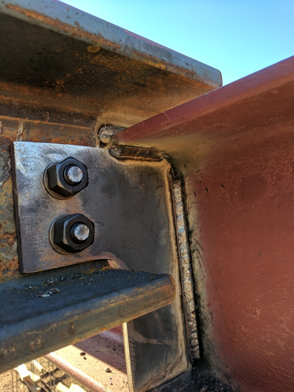
We have a field condition which we'll need to retrofit for a connection between a steel beam and supporting girder. The steel fabricator erected all of the steel before sending us shop drawings for review (we have told them this is not acceptable). As a result, we have an odd condition where the TOS for the beam is ~2 1/2" above the TOS for the girder. Had we reviewed the shop drawings we would have raised the TOS of the steel of the girder and avoided this condition.

The beam is a W8x67 and the girder is a W12x50 (don't ask -- residential construction). To make the connection the steel fabricator notched the W8x beam and welded the web of the beam to the top of the girder. They then installed a notched extended shear tab with (2)-3/4" A325N bolts to the web of the W8x beam. The loads are not extreme (~12k LRFD)
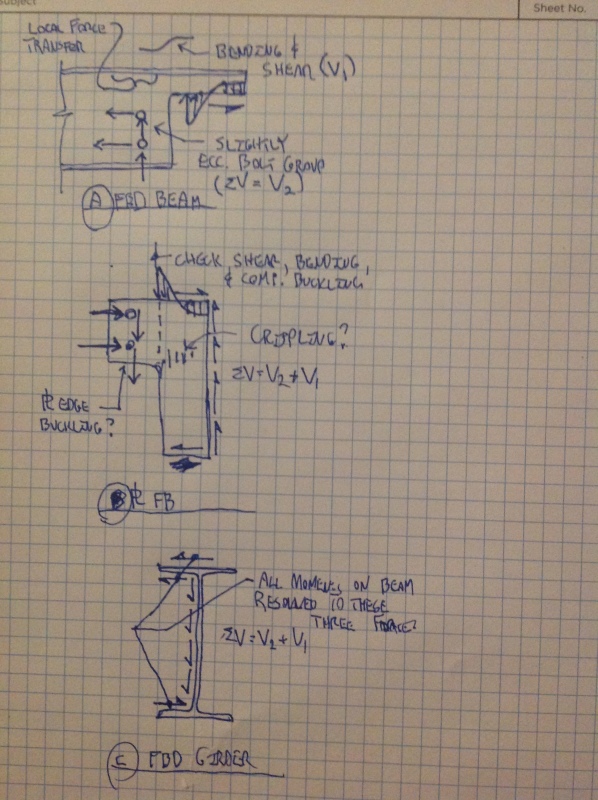
Now that the condition is constructed we are left trying to accept the connection or find a field fix. In my opinion there are currently two load paths:
1) Notched bearing seat
2) Extended shear tab
Due to unknown potential differences in stiffness I want to resolve the connection solely with one of these two load paths (i.e. not combining two). The notched bearing seat almost calcs outs (works for shear but fails in flexure if we assume the reaction point is at the web of the W12x to avoid introducing torsion into the beam). It fails by ~5% so it's pretty close. However, the notch is pretty extreme and almost the entire web is cut out. Even if it calced out I'm not sure how comfortable I would be with it.
Therefore, I'm left trying to get this to work through the extended shear tab. With the notched bearing seat I believe we have lost the rotational ductility of the connection and it should be considered "fixed" now. However, due to the fact it is a single-sided connection introducing torsion into the girder I don't believe the moments would be significant as a result. Therefore, I'm not overly considered about the rotational ductility of the connection as I believe the adjacent girder will provide an essentially "pinned" reaction.
Counting only the extended shear tab RISA Connection says the connection fails with DCR = 3.2. This failure is due to plate flexural failure as well as eccentric bolt failure.
As a fix, I can think of three potential options
1) Weld the backside of the shear tab to the web of the beam. This significantly reduces the eccentricity
of the connection. However, the line weld is not capable of resolving the torsion on it's own. I could then also weld the other 3 sides of the shear tab to provide better torsional resistance. However, in order to avoid plate flexural failure I'd need to assume the vertical force is resolved by the inside weld and the other 3 welds only provide moment resistance. Considering the difference in stiffness between the beam and the shear tab I think it could make sense, but I'm not sure how comfortable I am with this approach. This would be the easiest fix though. Normally, I know welding shear tabs is a bad idea, but due to the inherent flexibility of the supporting girder in torsion it seems to me to be acceptable in this instance.
2) Provide another shear tab on the other side of the web. In order to get the flexural strength of the plate to calc out, this plate would need to be 7/8" thick. The 3/8" plate and 7/8" plate would be able to act in unison and the bolts would be in "double-shear" (sorta). I would design each plate to take the load based on their stiffness (i.e. thickness of plate) and check the bolt reaction based on this stiffness assumption (therefore not truly double shear). The 2nd shear tab would then be PJP welded to the web of the girder / flanges on 3 sides. The bolts would need to be swapped out with longer A490X bolts.
3) Similar to #2 but abandon the bolts and weld web to shear tab.
I'm leaning towards Option #2. Any thoughts?

