Andrew,
Thanks for the attachment of the Feature Of Size definition from the new standard. I took notice that there is a definition of the term "Interruption" in the standard. It is a good sign because since it is defined, it is probably further addressed in other places in the standard - something that I felt was missing previously.
chez311 said:
I would probably just forgo any possible argument/issues with inspection down the line and specify it as profile if possible
I envy you
")
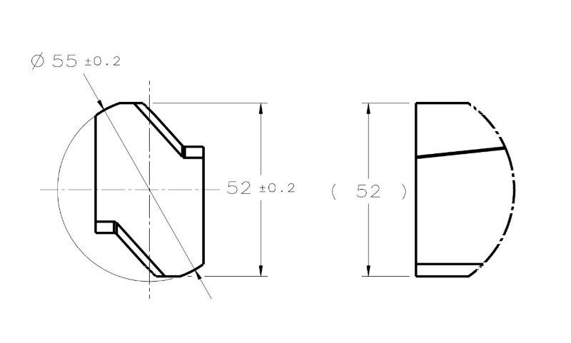
Our inspection does not know how to "digest" Profile tolerance. For the 2 flat surfaces 52mm apart, they would not have any issues at all if a horrible thing like 2X 26+-0.1 was specified between the axis and the surface. But they would probably raise questions about a basic 52 and a Profile call out referencing an axis datum and a clocking datum, because they think that Profile is intended mostly to control an accurate
form (not location) of features with complex contours and always requires the use of CMMs and programming and what-not. Unfortunately, I don't know enough about metrology to convince anyone otherwise. But these are "my" special case problems, and I agree that ideally, Profile would be a better choice to avoid any "legality" issues.
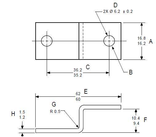
Kedu, thanks for the reference, these are some interesting quotes from the linkedin discussion. "E" does resemble the feature from my case dimensioned by 52+-0.2.
chez311, Kedu, I have my doubts about this statement from the linkedin discussion:
"E and F are not irregular features of size either. For these two be irregular features of size the mating envelope - two parallel planes - would need to able to close down on these faces. With these geometry closings parallel planes about the part surfaces would pitch ( or rotate) the part and would not actually close down on these faces"
"F" is obviously not a Feature Of Size. As for "E", I'm less convinced by the quoted argument.
For this type of geometry, the mating envelope would have to be simulated as part of an inspection of Position control (or a center plane orientation control, for that matter). When simulated by physical gauging equipment, the part will have to be immobilized in a fixture with its' degrees of freedom constrained according to the referenced DRF. The specified DRF can prevent the rotation of the part during the simulation of the actual mating envelope, and there might not be an issue at all. Am I missing something?