Hi!
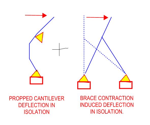
Suppose you have a frame like the enclosed picture
If I want to calculate the equivalent stiffness of the columns and bracing is it correct use the following stifnness':
k_col = E*I/L1^3
k_brace = E*A/L2*cos^2(45deg)
k_eq = 4*k_col + 8*k_brace --> Not sure about summing these stiffness' ?
( in 3D I have 4 columns and 2 brace mebmbers pr. column, one as shown and the other out of the picture plane)
Once k_eq is known the system can be modeled as a cantiviler beam with a mass on top?
Thank you!
Regards
Siggi
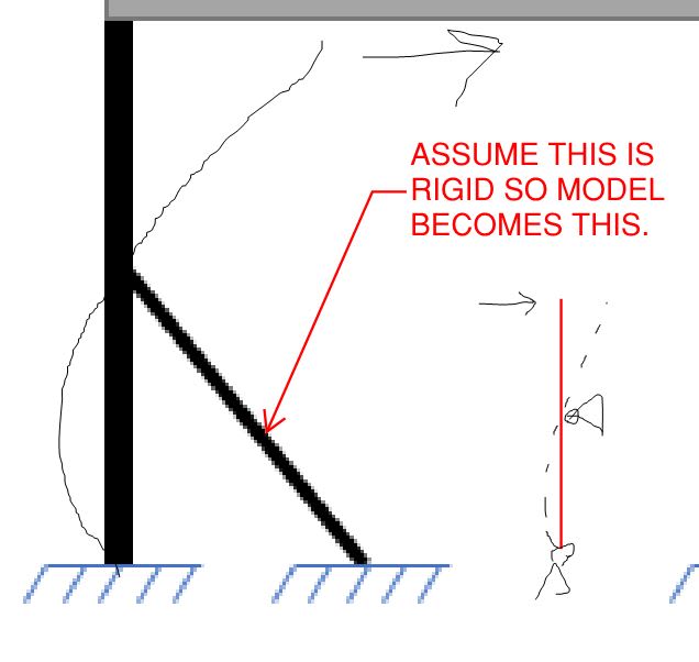
") You don't need computer to perform the unit load analysis, I bet BA can teach you the classic method by hand, as it is his strong suit
You don't need computer to perform the unit load analysis, I bet BA can teach you the classic method by hand, as it is his strong suit