Sa-Ro,
I have general comments about your drawing...
[ul]
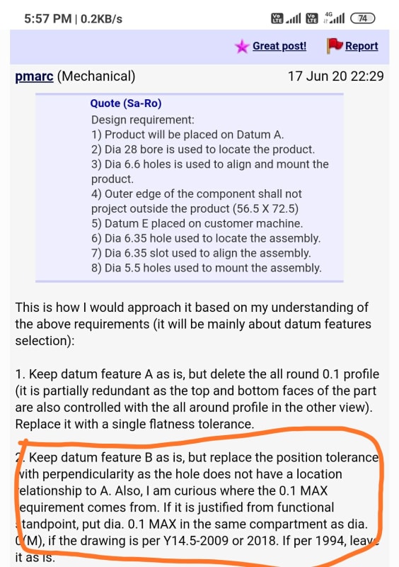
[li]I agree with the others that you need a positional tolerance on your 4.5mm holes.[/li]
[li]I like zero positional tolerances at MMC/MMB, but I make a point of specifying a sloppy maximum diameter. The ISO H14 tolerance is +0.3/0mm. The fabricator must make an oversized hole to allow for positional error, and allow for drill tolerances. You have not provided much room.[/li]
[li]33mm is a basic dimension, especially if you use positional tolerances as recommmended elsewhere.[/li]
[li]The notation "TYP" is not part of the ASME Y14.5 standard. Typing in the quantity of features sometimes is a pain, but it explicitly controls all the features. It is good practise.[/li]
[/ul]
A couple of practical notes...
[ul]
[li]Machine shops systematically clean up sharp edges, even if you don't tell them to. When you demand accurate chamfers on both ends of a hole, you may be forcing an additional machine setup.[/li]
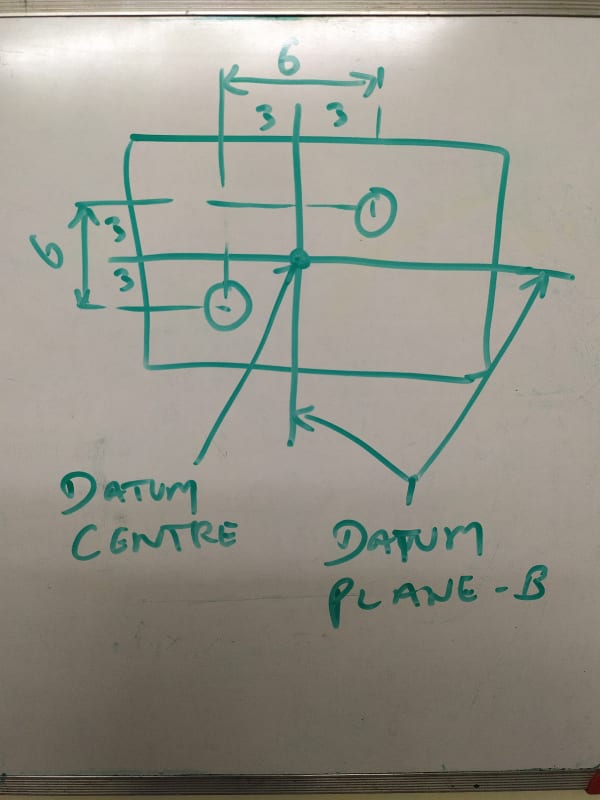
[li]You are calling up datum[ ]B at MMC/MMB. This complies with ASME[ ]Y14.5, but just how much of a bonus are you offering? If I use an FOS as a datum feature, I try to select something accurate. Datum[ ]B is way more meaningful if you open up the holes as I noted above.[/li]
[li]When I call up chamfers, my preferred method is to show the two linear dimensions, and configure the view so that the chamfers are controlled by a profile tolerance. My next choice is to use SolidWorks' chamfer specification. If a feature is controlled by an FCF somewhere, the angle specification should come from the datum feature. What you have done is not wrong, but I consider it ugly.[/li]
[/ul]
--
JHG