Continue to Site

Eng-Tips is the largest engineering community on the Internet

Intelligent Work Forums for Engineering Professionals

  • Congratulations waross on being selected by the Eng-Tips community for having the most helpful posts in the forums last week. Way to Go!

Default Position Tolerance for Features of Size

Status
Not open for further replies.

goz304

Mechanical
May 22, 2019
3
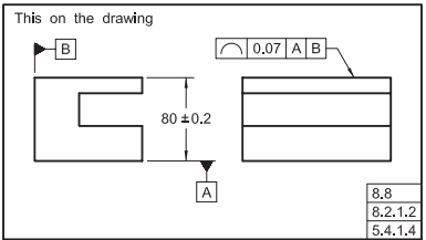
When applying tolerances using MBD, is it valid to define a plus/minus tolerance on a feature of size, say a hole, and allow the general tolerance to control its position? The general tolerance is a profile tolerance that is listed in the notes as applying to all features and surfaces unless otherwise specified. I have been unable to find information in 14.5 or 14.41 related to this. Can a profile tolerance just control position of a feature if it's size tolerance is already defined?
 
Replies continue below

Recommended for you

When you say that a plus/minus tolerance defines the feature of size, we presume you mean the size of the FOS (not location), so that is OK. And a general position tolerance could then be imposed via a note to control its location.
But if you want to have profile control the location of the hole, the problem is that profile also strong-arms the size of the hole into the same tolerance. So you can't use profile on a hole if the hole itself has a plus/minus on its diameter.

The best statement of this in the Y14.5 standard, 2009 edition, would be paragraph 8.2 where it mentions that profile must be applied to a "true profile." A true profile is one that is pre-defined by basic dimensions on the size/diameter.
In the new 2018 edition of that standard it would be paragraph 11.2.

John-Paul Belanger
Certified Sr. GD&T Professional
Geometric Learning Systems
 
I am troubled by the statement highlighted in green in the attached image. I read the phrase "Where used as a refinement of a size tolerance created by toleranced dimensions" as indicating that a feature of size, such as a hole with its size defined by a diameter with plus/minus tolerance, can also somehow have a profile tolerance applied to its boundary. Intuitively I agree with your assessment, this doesn't make sense to me.

Also, if both default position and default profile tolerances are specified, would the default position tolerance only apply to features of size with toleranced size dimensions? Let's say there are some features of size that I want to be controlled only by the default profile tolerance. If no size dimensions are applied to these features, will the size, position, orientation, and form be controlled just by the default profile, or would both the general position and general profile tolerance apply such that general position controls position and general profile controls size, orientation, and form? Or perhaps none of the above?
 
 https://files.engineering.com/getfile.aspx?folder=6c407e60-9bbb-4121-960f-76fe4cc61971&file=Profile_1_(1).jpg
I guess I would point to Fig. 8-27 of that standard as an example for your green text. The size (height) of the part is given with plus/minus tolerancing. But the GD&T is not attempting to control the height so the profile tolerance can indeed work in conjunction with plus/minus size tolerance. IOW, the green statement simply means that the 0.7 profile zones can float around within the 0.4 size tolerance.
For your example, though, the profile would be wrapping around a hole which is directly tolerance by plus/minus. That's what to me seems like a conflict.

That said, there have been a few discussions here over the years about Figure 8-18! In that case there IS a plus/minus tolerance on the diameter, and yet they used profile. Some of use have contended that this isn't really in line with paragraph 8.2, and in the 2018 edition that picture was reworked into a new concept called "dynamic profile," which permits the refined profile tolerance to expand/contract within a larger, fixed profile zone. Problem solved.

John-Paul Belanger
Certified Sr. GD&T Professional
Geometric Learning Systems
 
Belanger,

Are you saying that a hole cannot have both a toleranced diameter and a basic diameter at the same time?


pylfrm
 
Belanger,

Excellent, thank you for the info. I don't have a copy of the 2018 standard, so I will have to go take a look at that. Do you have any thoughts on my questions about how things would be handled with both a default profile and default position tolerance? This would help further simplify my MBD definitions, but it is not something that seems to be in general use right now. I guess it may be best to just define position tolerances individually for all features of size that have toleranced sizes.

An interesting note is that the Solidworks MBD tolerance status tool shows a hole with just a size dimension as fully defined when the part also has a general profile tolerance. I'm curious as to what interpretation is used in the program.
 
For what is worth I found some good examples here:


But none of them have default position (or at least the ones I open)

goz304 said:
The general tolerance is a profile tolerance that is listed in the notes as applying to all features and surfaces unless otherwise specified

The examples shown have default profile applied to all untoleranced surfaces (not features).
 
pylfrm said:
Are you saying that a hole cannot have both a toleranced diameter and a basic diameter at the same time?

pylfrm,

Do you think that is a good practice? I am just asking.

Any good examples, in the standards you can think of? I could not find any at this point.

 
greenimi,

Imagine a drawing with the following general notes:
1. 3D MODEL IS BASIC.
2. [box]profile[/box][box]1.2[/box] ALL SURFACES.

With a single hole dimensioned as follows:
diameter 8.6 +/- 0.3​

And with the associated 3D model showing 8.6 for the hole diameter.

I'm not saying this is a good way to encode some particular set of functional requirements, but it doesn't seem problematic for drawing interpretation.

I don't know of an example in a standard, but I imagine this sort of situation would be fairly common with minimally dimensioned drawings and model-based definition.


Also, if both default position and default profile tolerances are specified, would the default position tolerance only apply to features of size with toleranced size dimensions?

That depends entirely on how those default requirements are written.

It's very easy to introduce ambiguity with a statement like "UNLESS OTHERWISE SPECIFIED". In your case it's probably not clear what exactly counts as "otherwise specified". There are probably better ways to specify what you want.

I'd be hesitant to use anything like a default position tolerance. It seems much less useful and much more prone to interpretation issues than a well-written profile requirement.


pylfrm
 
pylfrm -- does that general note apply always and everywhere for the part? Or should that note imply "unless otherwise specified"? I ask because the scenario you describe seems to set up an internal conflict.

goz304 -- I know of a couple of companies where they'll have general GD&T callouts similar to that, but they break it down to say something similar to:
all circular FOS (pos)|Ø.005(M)|A|B|C
all non-circular FOS (pos)|.005(M)|A|B|C
all form surfaces (profSurf)|.010|A|B|C

I'd have to think more about your notation, but that's what comes to mind when you pose that question.

John-Paul Belanger
Certified Sr. GD&T Professional
Geometric Learning Systems
 
Belanger,

"ALL SURFACES" seems pretty clear to me. I intentionally did not include any exceptions.

Where's the conflict? I doubt you'd say a profile tolerance conflicts with, say, a cylindricity tolerance. Why should a size tolerance be any different? Each tolerance can be considered completely independently.


pylfrm
 
My reply to your cylindricity would then surprise you :)

It boils down to this: Profile must be applied to a true profile.
In your scenario (either the MBD one or the cylindricity example), is profile being applied to a true profile?

John-Paul Belanger
Certified Sr. GD&T Professional
Geometric Learning Systems
 
Belanger,

Interesting. Do you also see a conflict in ASME Y14.5-2009 Fig. 4-4 between the profile, parallelism, and flatness tolerances applied to datum feature C?

Anyway, in my example the profile tolerance is indeed applied to a true profile, which is defined by the 3D model for the entire part per note 1. Perhaps something like "3D MODEL DEFINES BASIC GEOMETRY FOR ALL SURFACES" would be a better way to phrase it, but the point stands.


pylfrm
 
If I may interrupt, in case of cylindricity, could we imagine cone with basic angle of zero? :)

"For every expert there is an equal and opposite expert"
Arthur C. Clarke Profiles of the future

 
Do you also see a conflict in ASME Y14.5-2009 Fig. 4-4 between the profile, parallelism, and flatness tolerances applied to datum feature C?
No conflict at all within Fig. 4-4. (That profile tolerance is applied to a "true profile" -- a nominally flat surface with a basic dimension of zero.)
The issue with yours is that the profile tolerance is being imposed onto a feature of size by having that extra ± tolerance.


in my example the profile tolerance is indeed applied to a true profile
No, because a true profile is defined by basic dims. You have a basic dim per the note, but then have a ± tolerance applied to it. Thus the internal conflict.

It's OK to have ± tolerances on dimensions that locate profile back to datums, but not OK to have ± tolerances on the actual geometry defining the profiled feature itself (with some rare exceptions, such as a cone with no datum references).


John-Paul Belanger
Certified Sr. GD&T Professional
Geometric Learning Systems
 
pylfrm said:
Imagine a drawing with the following general notes:

1. 3D MODEL IS BASIC.
2. profile1.2 ALL SURFACES.


With a single hole dimensioned as follows:

diameter 8.6 +/- 0.3

And with the associated 3D model showing 8.6 for the hole diameter.

I'm not saying this is a good way to encode some particular set of functional requirements, but it doesn't seem problematic for drawing interpretation.

Pylfrm,
I see one problem here:
Per Ø8.6±0.3 (and assuming ASME) perfect form at MMC is required, but no perpefct form at LMC needed.
Per 3D model showing 8.6 for the hole diameter, I go per Note 1 and say 8.6 is basic and then consequently and in conjunction with note 2 I would read: perfect form at MMC AND perfect form at LMC are both required.
Conflict right there.


pylfrm said:
I'd be hesitant to use anything like a default position tolerance. It seems much less useful and much more prone to interpretation issues than a well-written profile requirement.

Could you, please, develop a little bit more this subject.
I am not saying there are no problems with its interpretation, but I am asking where the issues could be.
Why default position could be a problem, in your opinion?

Belanger,

Could you give us more details on how DO YOU recommend to use default position within Y14.5?
As OP stated, I never seen depicted in the standard, but what could be potential problems the companies could face when try to use it?


Belanger said:
not OK to have ± tolerances on the actual geometry defining the profiled feature itself (with some rare exceptions, such as a cone with no datum references)

Is it really that rare?

Capture_qfxjbj.png


It's just I was always big fan of broader interpretation:

Profiles_mirklb.jpg


"For every expert there is an equal and opposite expert"
Arthur C. Clarke Profiles of the future
 
CH -- read my post again carefully, please: "It's OK to have ± tolerances on dimensions that locate profile back to datums."
That describes each of the snippets you gave. But notice that on each of those, the geometry of the surface itself is basic (zero).

John-Paul Belanger
Certified Sr. GD&T Professional
Geometric Learning Systems
 
Belanger said:
"It's OK to have ± tolerances on dimensions that locate profile back to datums." That describes each of the snippets you gave.

Except for the snippets that have no datum at all


"For every expert there is an equal and opposite expert"
Arthur C. Clarke Profiles of the future

 
Just to stir the pot:
CH set of pictures are taken from G Henzold’s book:” Geometrical Dimensioning and Tolerancing for Design, Manufacturing and Inspection”

We have noticed and talked on this forum multiple times, that different authors have different interpretations about what is shown in the standard. Henzold’s book is no exception. It is, unfortunately, full of mistakes and I was told to stay away from it as much as possible. There are way better books on the market then this one.

Sorry to be rude.
 
Status
Not open for further replies.

Part and Inventory Search

Sponsor