chez311,
I think you're missing the point here. It is not really about what interpretation takes precedence for conformance.
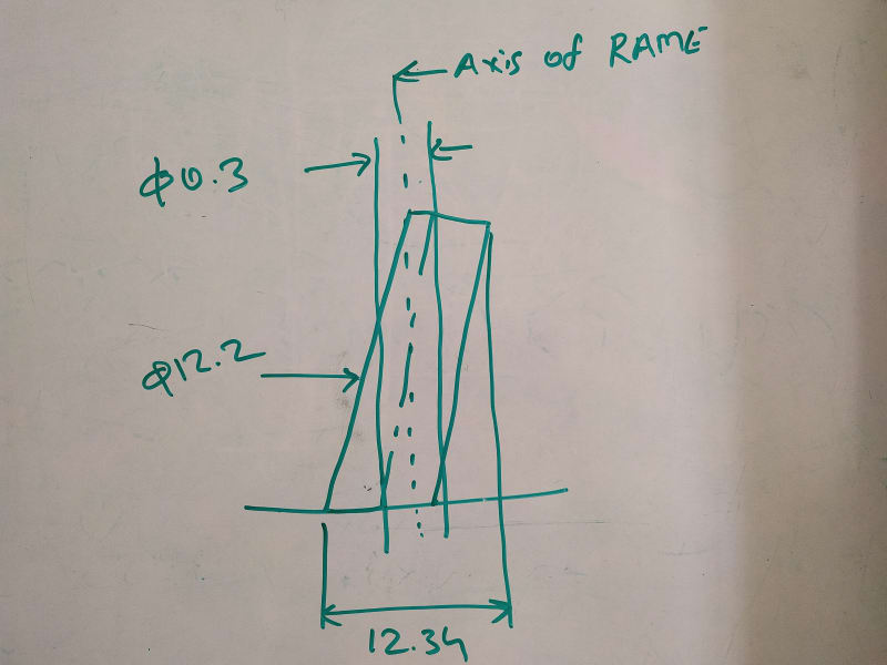
My speaking of one type of evaluation being an approximation of the other is in the context of what was explained to Sa-Ro, and that is how to evaluate the RAME size of a feature assuming that it is out of true position within a specific amount of tolerance (0.3) due to an error in axis orientation. See his
sketch from 7 Jun 20 03:41.
Sorry for repeating my question again, but if you think that since Sa-Ro introduced the problem dealing with an axis, there is a way to quickly evaluate based on Y14.5 that the RAME of the feature should be near 12.5 (without CAD models or overkill trigonometry) which is better / more correct than using the same formula that the calculation of the limiting boundary for the surface interpretation is based on, please share. Otherwise if like me, the first thing you would do is to add the value of the utilized position tolerance shown in his sketch to the MMC limit (12.2+0.3), then you should know that the link between the two interpretations is unbreakable, and honestly I have no idea what point you are trying to make here. Sure axis and surface produce different results to some level of discrepancy, and it's true that one takes precedence over the other for conformance, but is any value added by all that here considering the problem?
Note taken that form error is an additional factor and that there is no way to tell which requirement is more stringent as it would depend on the exact situation, but that only confirms that there is no way to tell for sure if a realistic feature which is similar to the one in Sa-Ro's question but not identical to my simplistic sketch would pass or fail the inspection with the hard gage shown in the video. As I mentioned to Sa-Ro, it's a borderline situation and there is no reason to assume a realistic feature would not conform. Since the borderline pass/fail condition is the same for both the axis and surface interpretations, this further emphasizes their connection. In the end, there is a good reason why para. 7.3.3.1 in the 2009 standard calls them "Surface
Interpretation" and "Axis or Center Plane
Interpretation" - that is to say, the interpretation changes but the concept remains the same.
chez311 said:
It has a much smaller effect on the size of the RAME, and it was clearly not the conclusion the question was meant to elicit (actually you didn't even go out to enough decimal places in your initial response to make this conclusion either)
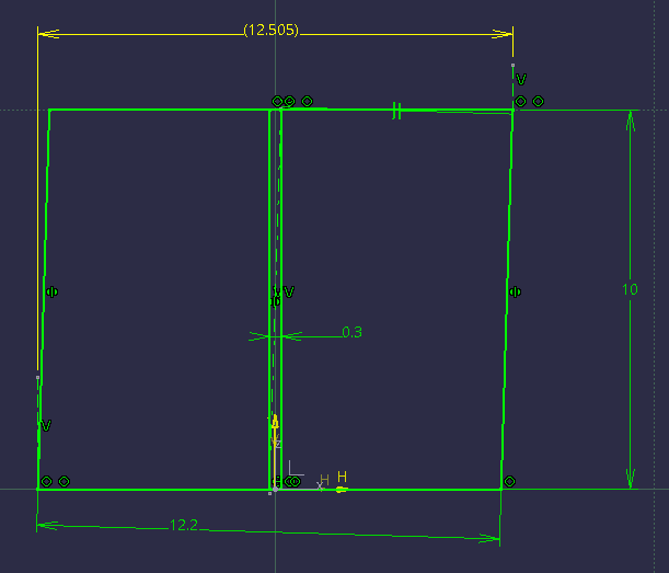
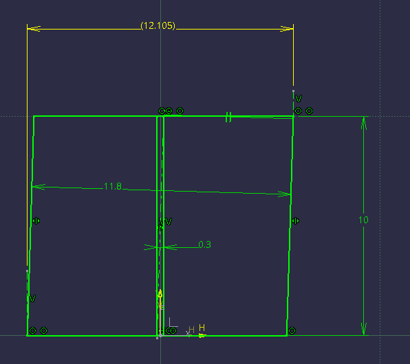
As admitted already, I suppose I didn't do a good job at guessing pmarc's intent. However as you've seen there are also other nuances to the subject beside of the maximum possible RAME size, and since "maximum" or "extreme" wasn't mentioned it was also reasonable to think that the intent was to examine the relationship between UAME size difference and the resulting RAME size difference for the specific orientation error that was discussed. And by the way, both the sketches I made show 3 decimal places for the RAME size.