Continue to Site

Eng-Tips is the largest engineering community on the Internet

Intelligent Work Forums for Engineering Professionals

  • Congratulations cowski on being selected by the Eng-Tips community for having the most helpful posts in the forums last week. Way to Go!

Datum Shift question

Status
Not open for further replies.

pyromech

Mechanical
Jul 30, 2008
39
Folks

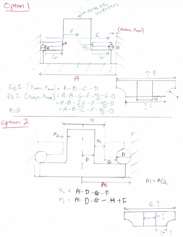
I am trying to find the max/min distance and I am not sure if this approach is the best one. Please doublecheck.. Lets assume the mating features are perpendicular so we can rule out any tilting and datum features dont need to be perpendicular, thats a new one..
Datum Shift, Line D, are we using the centerline approach for datum B. I didnt include all the parts in the stack path which i think i should.

thanks, appreciate the feedback
 
 http://files.engineering.com/getfile.aspx?folder=30260924-60d5-46e1-b46b-dfba3e527b5b&file=Book2.pdf
Replies continue below

Recommended for you

Whatever datum shift there is in the pocket, it doesn't matter. What matters is the .682 diameter that is in the vector path. Without knowing what the third part is and what its characteristics are, it's not clear what that gap might be.
 
Lets say, the DIA 0.682 (swivel) will be rotating at 70 hz from pull force. I guess i am taking Alex book too literally
 
3DDave said:
What matters is the .682 diameter that is in the vector path
Hi 3DDave

Here are two stack path. The ball is standard 1/16" diameter. I am doing reverse engineering. We know the max,min gap which is our design requirement. I am trying to design the washer dimensions from scratch. I opted for option 1 but i cant seem to position the parts at its minimum gap. At the maximum, the shaft touches the washer (see x). The balls always touch the wall cavity first. the washer (dimension E) and the shaft bottom never touch the wall. In option 1, two loops and two unknowns (C, H while F is known). But i also need to find dimension E. My question is do I account for the difference between the centerlines of the shaft(Dim F)-Dimension H which i dont know and will probably have a position feature frame. I seen stacks where they account for this delta. Equation 2 has two unknowns which can be tweaked by trial and error to meet the gap. I dont see any use for equation 1 unless to find C and then use it in equation 2 to find H?

I am afraid option 2 is incorrect because x1(xmax)is ignoring H and x2 has the wrong signs, it should be x2=D+G+H-A1-F. I dont know what to do, help


path5_rsn3iz.png
 
I'm having trouble reverse engineering your reverse engineering diagram. The washer resting on ball bearings doesn't constrain the washer and the shaft is not restrained.

The equations don't make sense. E isn't in the path for X1 or X2.
 
3DDave said:
The washer resting on ball bearings doesn't constrain the washer and the shaft is not restrained
. you mean option 2 restrains the shaft?. yes, i corrected the graph, E should not be in path, letter mismatch. Option 2 was proposed but my reservations is the shift between shaft and washer hole (dimension H) which option 2 doesnt count for.
thanks

 
Status
Not open for further replies.

Part and Inventory Search

Sponsor