Continue to Site

Eng-Tips is the largest engineering community on the Internet

Intelligent Work Forums for Engineering Professionals

  • Congratulations waross on being selected by the Eng-Tips community for having the most helpful posts in the forums last week. Way to Go!

datum feature interpretation

Status
Not open for further replies.

AndrewTT

Mechanical
Jul 14, 2016
261
I sent a RFQ for a wrench to a Chinese vendor. This vendor has made similar wrenches for us before. We are basically brand new to using GD&T. I know that this vendor has seen GD&T before but I do not know their level of expertise (especially w.r.t. ASME Y14.5-2009).

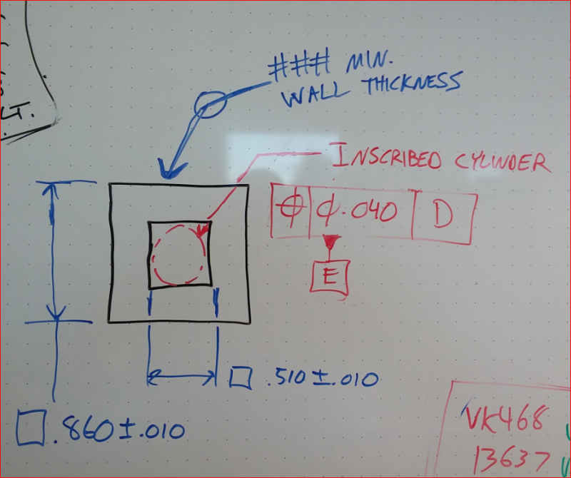
The vendor's proposed changes are on the attached drawing. Their feedback is in yellow. What I would like to discuss is their replacement of my profile tolerances on the square boss and square hole with position tolerances (as seen in the upper most view). Of course, what I am after is that both square features are oriented to each other to maintain a nominally uniform wall thickness between the boss and the hole and that both square features are centered on the part.

While I believe that the proposed position tolerances still achieve this I am wondering if the interpretation of what datum feature "E" is has changed. With the original profile tolerance datum feature "E" is the square hole. Does using the 2X Ø.510 as datum feature "E" achieve the same thing? Does anyone read that datum feature "E" is only one set of opposed surfaces and not both sets of opposed surfaces?

I am thinking that I will add a note to the datum feature symbol stating that datum feature "E" is the square hole just to be safe.
 
 http://files.engineering.com/getfile.aspx?folder=300ecc3f-f2f1-4610-9e31-9bddb797f654&file=wrench_for_forum.pdf
Replies continue below

Recommended for you

Lol, that exact same response would happen here before I even finished my sentence.
 
Capture_pm_zjfsuw.png


pmarc said:
on your latest sketch, what prevents the square features from being produced as rhombuses (parallelograms with sides of approximately equal length but with no right angles)?

pmarc,
This was the latest sketch back then:

I have a follow up question, if you don't mind: why the parallelogram's sides perpendicularity is not restricted by the 90 degrees implied angle and the title block tolerance angle? As I can see the title block has a default angle tolerance and the default 90 angle is known.
 
greenimi,
I suggested that the perpendicularity error of the sides was not controlled simply because I did not notice that there is a general tolerance for angles in the title block ;-)
 
pmarc said:
The open point would then be what "standard 1/2" square socket drive" really means.

ASA B5.38? ISO 1174? IS 7214? IS 7996? DIN 3120? DIN 3121? There sure are a lot of options...


AndrewTT said:
pmarc - Attached is the current drawing. The problem that you address is still present.

possible fixes:
1) Change position FCFs of square hole to zero at MMC.
2) Compound profile control for square hole.

Position tolerances of zero at MMC sound like a reasonable approach to me, especially since profile apparently won't fly. You'd probably want to do this without datum feature references to avoid creating an overly-restrictive requirement. The scheme used for datum feature A in ASME Y14.5-2009 Fig. 4-24 should work, along with other tolerances to control the relationship to the rest of the part. These could be combined into a composite FCF if desired.

Side note: Datum feature D seems awfully short for use as a primary datum feature, especially if it might have significant form error.


pylfrm
 
plyfrm - I was thinking position of .000 @ MMC to datum D at MMB for each set of opposed parallel surfaces of the square hole (to avoid being overly restrictive).

Originally I was going to use the entire large cylinder as a datum feature. Then we scanned similar wrenches that we had from that supplier. They are more banana shaped then a true cylinder. That is why I broke up the cylinder into smaller chunks. Really I only need the opening that interfaces with the part-to-be-installed to be centered to the lower end of the cylinder and the socket-interface to be centered to the top of the cylinder.
 
AndrewTT,

I didn't specify, but I was actually thinking that datum feature D seems awfully short for use as primary when referenced RFS. For instance if the length is .200 and the diameter is toleranced as 1.800 +/- .010, then the actual part surface could be spherical. This would make it incapable of constraining orientation, and the remaining translational constraint would not be very meaningful.

If referenced at MMB, form error isn't even required for the same problem to show up. The actual size just needs to be sufficiently smaller than the MMB size. An actual diameter of 1.798 would be small enough with my example dimensions.


EDIT: 1.798 was 1.978
 
Status
Not open for further replies.

Part and Inventory Search

Sponsor