Tek-Tips is the largest IT community on the Internet today!

Members share and learn making Tek-Tips Forums the best source of peer-reviewed technical information on the Internet!

  • Congratulations cowski on being selected by the Eng-Tips community for having the most helpful posts in the forums last week. Way to Go!

Cylindrical feature, datum symbol placement, in line vs not in line with dimension arrow 4

tN.gineer

Mechanical
Joined
Sep 24, 2023
Messages
2
Location
CA
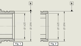
Greetings Forum, I have a simple question about the placement of a datum symbol for a cylindrical feature: Is there any difference in the datum defined by Datum Feature B as indicated in the two figures below? Is either acceptable or only fig. 1?
1751484372963.png
I know that if the 1.894 dimension was the distance between two planar surfaces instead of a cylinder diameter, then these mean very different things, but what about for a cylinder?

Thanks!
 
The right hand side is what is used to identify a plane that is tangent to the cylinder.
The left hand side is what is used to identify the axis of the cylinder.

In two planar surfaces, one identifies one face and the other identifies a plane in the center.
 
Ah ok, I would not have guessed that a plane tangent to the cylinder would be described by fig. 2 but I guess that makes sense... though I'm not sure when one might use that. Thank you!
 
Here are the relevant definitions from ASME Y14.5-2018:

" (d) placed on the dimension line or an extension of the dimension line of a feature of size when the datum is an axis or center plane. If there is insufficient space for the two arrows, one arrow may be replaced by the datum feature triangle. See Figure 6-4, illustrations (a) through (c), (f), and (h); Figure 7-40; and Figure 7-42, illutrations (c) and (d).

(e) placed on the outline of a cylindrical feature surface or an extension line of the feature outline, separated from the size dimension, when the datum is an axis. For curved features, the triangle may be tangent to the feature. See Figure 6-4, illustrations (e) and (g). "

Taken from
6.3.2.1 Datum Feature Symbol Application in Orthographic Views.

In your figure the left side is (d) and the right side essentially conforms to (e), although applied in a different way than the standard's example figures show (they show it on the circular outline of a side view of a cylindrical feature).
 
Last edited:
I was concerned but clearly the standard does not imply an axis with the right hand side example.

The right side clearly doesn't conform to (e).
 
I was concerned but clearly the standard does not imply an axis with the right hand side example.

The right side clearly doesn't conform to (e).
What else is the right side, if not " placed on the outline of a cylindrical feature surface or an extension line of the feature outline " ?
 
Burunduk's explanation is how I have understood it since my intro to Y14.5.
 
Greetings Forum, I have a simple question about the placement of a datum symbol for a cylindrical feature: Is there any difference in the datum defined by Datum Feature B as indicated in the two figures below? Is either acceptable or only fig. 1?
View attachment 14769
I know that if the 1.894 dimension was the distance between two planar surfaces instead of a cylinder diameter, then these mean very different things, but what about for a cylinder?

Thanks!

In order to avoid unnecessary discussions and arguments I will not recommend to use fig 2's approach.
There is no point to do it.
Make it crystal clear (fig 1) and move on.
Make it "ambiguous" (or less than clear) and then you will get people with arguments and justifications ....back and forth....
 
  • Like
Reactions: ewh
ewh, in that case how is the tangent plane identified? Also, it is an incompatible change from the other feature of size case and, more than that, raises the question of why alignment with the dimension is ever mentioned if it is unimportant.

It's been long the case the committee is really poor at writing, but they do supply graphic examples of the application of graphical symbols and have not chosen to show both cases, suggesting that there aren't "both cases" for the single interpretation.
 
The reason for the difference from a width in that sense - a width feature of size is two opposed parallel planar surfaces, and each of those surfaces could be potentially treated as a separate feature. So for a width, when the triangle of the datum feature symbol is offset from the dimension line, it changes the interpretation, because it changes the considered feature from a width to a single planar surface (to which the extension line pertains). The obtained datum also changes, from a center plane between two surfaces to a tangent plane to one surface.

A cylinder on the other hand, is one surface and cannot be broken down to different features. So the interpretation of what the feature is and what the associated datum may be does not change according to the different possible placements of the datum feature symbol.

I also agree with greenimi on this - I would not recommend the fig. 2 option.

I would stick to those:
1000025042.jpg
 
Last edited:
I too would not recommend it, but I think it's pretty clear in meaning the axis. Definition (e) does mention an extension line of a cylinder (which the right-hand figure shows) and (e) even says that it can be separated from the size dimension (the arrows). It doesn't say that such usage must be in the view where it appears as a circle.
For a tangent plane, my thinking is that you'd use a datum target line.
 
3DD - I'm only agreeing with what the standard says, not defending it.
 
Passive acceptance of garbage leads to more garbage. It's an unavoidable problem when there is a de facto monopoly on a graphical descriptive language that has a mismatch with the verbiage.

Anyway, great to have a defined condition that was not used anywhere in the standard, except, sort of Figure 6-3 where the difference between applying to the center plane versus just one face depends on exactly this difference in alignment.

Once again, round of applause to the creators.

It's also not new. It goes back to 1994, which also has no example figure, unlike all the other mentioned applications.
We need to be fair.
In defense of the Y14.5 subcommittee, it can be said that the standard explicitly states that the written text is what determines the requirements, and the absence of an illustrative figure does not invalidate any specific use. And you know you're welcome to submit suggestions to them on how to fill in the gaps.
 

Part and Inventory Search

Sponsor

Back
Top