Tek-Tips is the largest IT community on the Internet today!

Members share and learn making Tek-Tips Forums the best source of peer-reviewed technical information on the Internet!

  • Congratulations TugboatEng on being selected by the Eng-Tips community for having the most helpful posts in the forums last week. Way to Go!

Cylindrical coordinates in NX12

Status
Not open for further replies.

Itxusta

Mechanical
Joined
Apr 18, 2024
Messages
5
Location
ES
Hi,

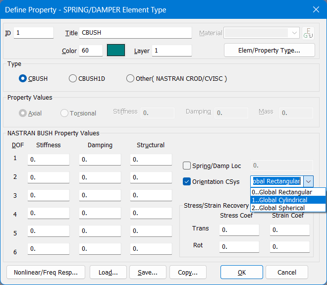
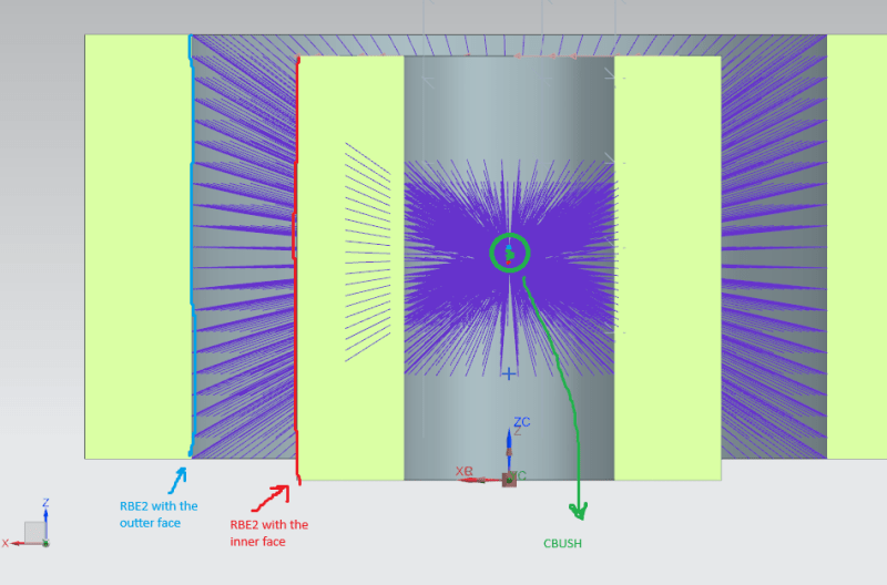
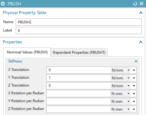
I am modelling a bearing in NX12, which I have done using RBE2 elements to connect the inner (red colour) and outter (blue colour) faces of the bearing with points in the center and then applying a CBUSH to connect the points (the green spring in the center connecting the blue and red dots). I want to apply the axial and radial stiffnesses to the CBUSH but I don't know which coordinates are the radial and axial ones.
Captura_de_pantalla_2024-05-06_160420_xavxol.png

Captura_de_pantalla_2024-05-06_161038_n7tstk.png


Thank you for your help!

Regards
 
you need to define a cylindrical coordinate systems, and then assign that system to the nodes.
 
I understand that, but which coordinate (x, Y or Z) of the PBUSH property table refers to the axial and radial coordinates of the new cylindrical coordinate system?

Thanks!
 
Dear Itxusta,
As told by SWCOMSITES you need to assign a cylindrical coordenate system (either local or global) to the properties of the CBUSH element.
This is the form we have in FEMAP with NASTRAN software bundle to define the properties of the CBUSH element, search for similar fields in NX CAE: once activated the cylindrical system in the PBUSH property the stiffness defined in X is radial.

CBUSH-COORDINATE-SYSTEM_u7afo7.png

Best regards,
Blas.

~~~~~~~~~~~~~~~~~~~~~~
Blas Molero Hidalgo
Ingeniero Industrial
Director

IBERISA
48004 BILBAO (SPAIN)
WEB: Blog de FEMAP & NX Nastran:
 
Thank you both for you quick responses, it works now!

Regards
 
Status
Not open for further replies.

Part and Inventory Search

Sponsor

Back
Top