Continue to Site

Eng-Tips is the largest engineering community on the Internet

Intelligent Work Forums for Engineering Professionals

  • Congratulations waross on being selected by the Eng-Tips community for having the most helpful posts in the forums last week. Way to Go!

Centerplane datum through a molded or die cast trough with a "V"-shaped cross section

Status
Not open for further replies.

Tunalover

Mechanical
Mar 28, 2002
1,179
Assume it would be possible to mold or die cast a trough of thickness T having a cross-section of a "V" shape. Using datum targets, how would one create a centerplane datum down the length of the trough bisecting the "V"-shaped cross section? I asked this question to several people and got different answers.

Tunalover
 
Replies continue below

Recommended for you

3DDave:
Doesn't matter. I just want to know how people would go about creating the bisecting datum using datum targets.


Tunalover
 
Does matter. When I was doing this same task I used a spherical datum target to simulate the spherical tooling ball on the mating part and a cylindrical datum target to simulate the mobility of a sphere along the groove.

It is fundamental to most designs that that dimensions and tolerances reflect the interface to the idealized mating parts. Without knowing the shape of the mating part there is no useful answer.

Given the lack of other replies, what other responses have you gotten?
 
tunalover,

Do you intend to use the V-groove as primary datum feature? If not, which degrees of freedom are already constrained?

I agree with 3DDave, the details of the application do matter. Keep them a secret and you will probably continue to get different answers from different people.

That being said, here's a random possibility for a primary datum feature: Use three datum target spheres, two of equal diameter and fixed, the third of different diameter and movable, and each making contact with the walls of the V-groove at two points of tangency.


pylfrm
 
OK, I guess I was trying to oversimplify it.

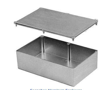
I am modifying a purchased die cast aluminum enclosure to add wall mount connectors (among other things). Here's the enclosure:

Capture_kmjems.png


The enclosure consists of a die cast lid and die cast box. All four sides of the box have like a 1.5° draft angle that, of course, makes it longer and wider at the top than at the bottom The box has a shelf on which the lid rests when it's installed and this shelf is recessed slightly down from the top rim. This shelf is parallel with the bottom surfaces.

There are connectors, panel mount switches, and panel mount indicator lights installed on all four sides of the box. I am only modifying the box portion. The lid is out of the picture.

Each side of the box will of course be the primary datum for the features in that particular side. The trick lies in establishing secondary and tertiary datums. If the box had no draft angle then I would use one center plane datum established using the length dimension and one center plane using the width dimension, use those datums as tertiary datums and take dimensions from those center planes. Also, if the box had no draft angle, I would use the bottom surface as my secondary datum for all four sides. But that's not the case.

Using datum targets if necessary, how would I establish secondary and tertiary datums? Also, if somebody could refer me to a good reference with detailed examples of how to dimension and tolerance cast and molded parts I'd be much obliged! Draft angles complicate things.

I hope my picture inserted properly into the body of the text as intended. If not, I attached the picture file capture.png.

Tunalover
 
The draft angles are small enough to be essentially ignored.

If the walls are 0.09 thick, then the difference is cos(1.5º)*.0.09 = 0.0064 (after rounding). A hole drilled parallel to the bottom will be reduced to sin(1.5º) (99.75%) of the diameter - the 0.0064 for 0.09 thickness; a 1 inch hole would accept a 0.991 pin held perpendicular to the sloped side.

The biggest challenge is if the holes need spot facing. If this was being made on a knee mill or something like it I would centerpunch with the bottom face as the primary datum feature for all 4 faces and the width of each side as the secondary datum feature, as they apply. This would set the location. Then put it on an angle plate attached to a rotary table to turn each face horizontal and use the centerpunch mark to located the feature for machining. If you like, set the Position tolerance to a diameter of, say. 0.030 with the bottom as the primary datum feature and the related width as a secondary RFS and a separate perpendicularity of some small diameter to each face as a datum feature. As I mentioned, you'll lose up to diameter 0.0064 (for a full .09 depth feature) due to the slope, so only 0.0236 vertically remains relative to the bottom, but that's plenty for switches and indicator lights.

It takes almost as much engineering and fixturing futzing for these pre-cast boxes on anything less than a 5 or 6 axis machine as it costs to cut one out of a block of aluminum on a CNC - and that cutting out can include all the features that the cast box is going on the mill for in the first place. It seems to me the savings are mostly offset by the additional handling and it's just that people dislike the amount of chips from a block. Making it from a block also means choosing an alloy you like, which is handy if you want to anodize it. It also allows for a material that has the mechanical properties one might like.

The only advantage some of them have is a molded, integral seals and some pretend to have emi trapping/excluding features. I prefer to select the appropriate seal and emi materials.
 
3DDave-
How can the draft angles be ignored? A DRF formed with the primary being any side face a secondary being the bottom, and a tertiary being an adjacent side would not form three mutually orthogonal planes. Would I need to also ignore the fundamental rules of GD&T?

Tunalover
 
I would not use any side face as a primary datum feature. I did not suggest you ignore any rules.

The draft angle is small enough to be essentially ignored, as in, if the a hole is drilled parallel to the bottom surface it will be nearly perpendicular to the side face - I gave an example of how to calculate the small amount by which it differs.

And if the bottom surface is the primary datum feature, then a hole drilled perpendicular to a side face will be almost parallel to that feature, and I gave an example of how to calculate the small amount by which that differs.

If there is something wrong with the math, then point it out. There is nothing wrong with the reasoning.

There's no rule that says the primary datum feature reference has got to be the surface a hole is made in, just a ton of examples where that happens to be true without explaining why it doesn't always have to be true.
 
3DDave-
OK. Maybe your approach is good enough for modifying a purchased die casting, but how would you handle it if some or all of the features I added above were part of an original die cast part and that the box itself had to be dimensioned and toleranced as well?

Tunalover
 
Status
Not open for further replies.

Part and Inventory Search

Sponsor