Continue to Site

Eng-Tips is the largest engineering community on the Internet

Intelligent Work Forums for Engineering Professionals

  • Congratulations cowski on being selected by the Eng-Tips community for having the most helpful posts in the forums last week. Way to Go!

Cantilever Transfer Slab, Would you design it this way? 5

Status
Not open for further replies.

I-I

Structural
Aug 31, 2020
9
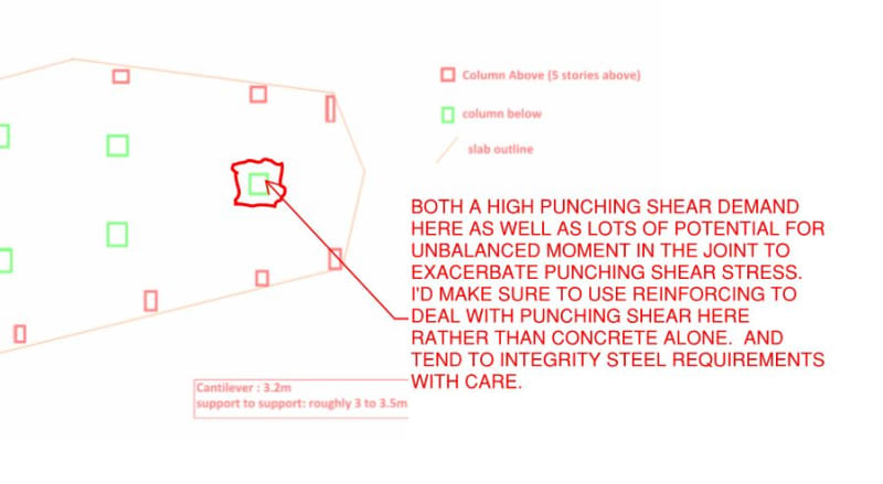
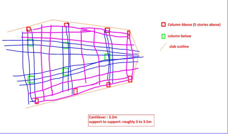
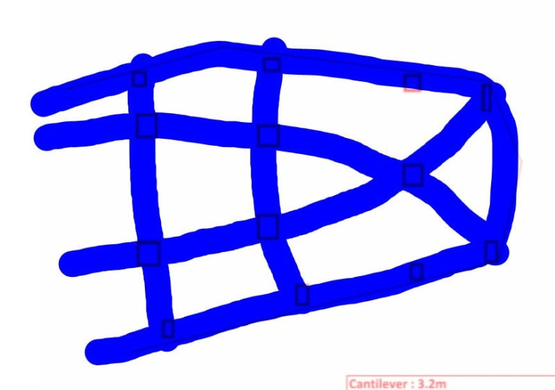
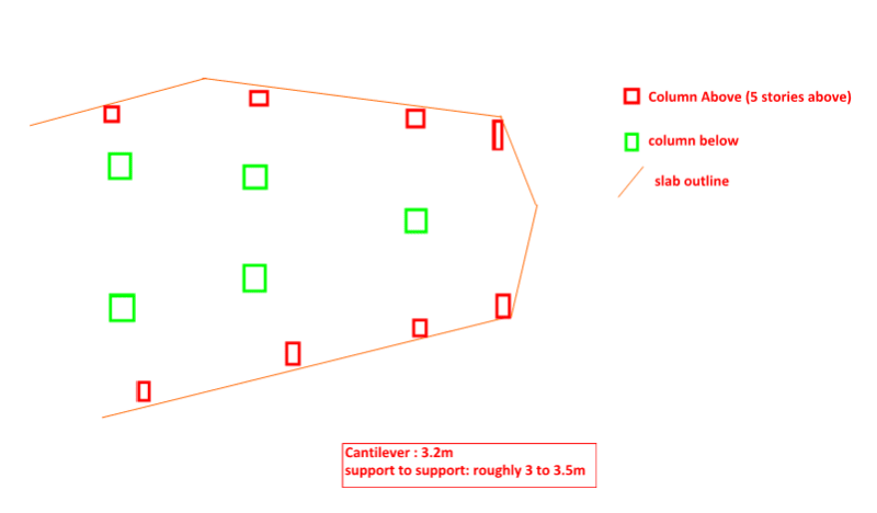
I have uploaded a sketch below showing the project I am designing, This transfer slab is going to support 5 stories above. Because there are bedroom above and I couldn't shift the columns above inwards so I have to put them on external and being supported by this transfer slab. The loads of each column above is roughly 200kN (Dead plus Live). Although I am not the one to design the PT transfer slab, I am not comfortable with this arrangement. But at the same time, I cannot shift the columns above 3.2 m inwards. (The columns below cannot move outwards they are on the external already, outside of them are roads)
What is your thoughts on this?
CAN_iabscr.png
 
Replies continue below

Recommended for you

What's you governing lateral force and what is the system in play

"Programming today is a race between software engineers striving to build bigger and better idiot-proof programs, and the Universe trying to produce bigger and better idiots. So far, the Universe is winning."
 
JLNJ said:
Looks like a teeter totter.

That.

I'd only be willing proceed with the concept if:

1) I could make it work with the column to slab connections modeled as pinned and;

2) I could maintain reasonable deflection control out at the cantilevers (true of all transfer slabs of course).
 
This is just the part plan at the corner. There are core walls and shear wall on left hand side.
 
Can you please elaborate on this? Do you mean the column above? Why should moment be avoided? (I don't think pinned connection can be achieved)
As for deflection, the PT designer will take care of it. The client is happy with increase the slab thickness in this area.

 
I-I said:
Can you please elaborate on this?

I'll sure try.

First, you get the whole teeter totter concern, right? If not, do let us know as that's pretty fundamental to all that follows.

So there will be two primary things preventing dreaded teeter totter behavior:

1) Axial force couples developed in the lower columns which is a very reliable mechanism and;

2) Moments developed between the slab and the columns above and below which I consider to be a much less reliable mechanism.

My thinking is this then: if you're gonna do the teeter totter thing, at least set it up so that it relies upon only reliable mechanisms.

I-I said:
I don't think pinned connection can be achieved

I agree. I'm not at all suggesting that you make the column to slab joints pins in real life. Rather, I'm recommending that you run one version of your analysis fictitiously discounting and moments that develop between the columns and the slab as a means of assessing that mechanism #1 above is sufficient.

 
I would send it back to the architect and tell him to start again.
 
Another concern that I have now that I look at it again.

C01_nbwoc1.jpg
 
We could certainly have some fun trying to game the best PT layout though...

C01_bkmmpn.jpg
 
Plan B.

Another thing to watch for is that you're treating slab torsion in a way that makes sens (wood armer etc). You don't want teeter totter prevention depending too much on a high risk, brittle torsion mechanism.

c02_uwnipb.jpg
 
Kootk,

The tendon arrangement is not the problem. A standard 2way pattern normally used in Australia could be made to work fairly easily.

Robustness is impossible to achieve. No-one should be encouraging a layout like this to proceed.
 
rapt said:
The tendon arrangement is not the problem.

I know it's not the problem rapt. Like I said, I was exploring the the possible PT layouts for fun.

KootK said:
We could certainly have some fun trying to game the best PT layout though...
 
Yeah. That is my concern. In another word, like rapt mentioned, the robustness.
But, even if I put the stories aside, i.e. just one story structure (or the col above shift inwards), the robustness is still an issue as it is still like a teeter totter a especially for the right corner with one column only. Am I right? If so, I don't think I can let the architect to do much on this as this is the shape of the building (cantilever slab on a triangular corner).


As everyone has pointed out there would be an unbalanced moment (due to loads from above) on the column below located the right-most side of the plan.

In addition to what others have said, I would likely design the above mentioned column as rigidly connected to the transfer slab and having fixed base to the foundation (i'm assuming column below is supported directly by foundation) in order to transfer the unbalanced force (I just dont see a way how will the unbalanced moment be transferred to the adjacent columns when base is pinned)
 
I think KootK's suggestion to widen the rightmost column is pretty good idea, if the architect agrees.
 
KootK

I would go for something more like this.

Support strip columns in blue. Secondary columns in mauve carrying loads to the support strips.

Capture_e3p2bu.jpg
 
Even if that column is increased significantly in size, you still have a robustness/disproportionate collapse issue. One column fails due to impact and 5 storeys come crashing down.

The pattern loading will of course give you HUGE out of balance column loading at transfer level. i.e on the day everyone on each of the 5 storeys runs to look out at the parade along the North elevation and no one is balancing it on the South!

Do architects even do structures modules in college these days?!
 
MIStructE_IRE said:
Even if that column is increased significantly in size, you still have a robustness/disproportionate collapse issue.

In the interest of Devil's advocacy on the robustness front:

1) I see this as, essentially, an extreme version of building corner column. We still have those, right? How is robustness resolved there and what makes this so different?

2) This setup actually has one advantage over a conventional corner column: the integrity steel can be very well anchored beyond the column.

3) If this system were mild RC beam and column, as shown below, I'd be reluctant to veto the thing. Given that OP's slab will have to be very thick for deflection control, he may well be able to do something quite similar as in-slab beams.

C01_ej3mla.jpg
 
Status
Not open for further replies.

Part and Inventory Search

Sponsor