Continue to Site

Eng-Tips is the largest engineering community on the Internet

Intelligent Work Forums for Engineering Professionals

  • Congratulations cowski on being selected by the Eng-Tips community for having the most helpful posts in the forums last week. Way to Go!

Cantilever Transfer Slab, Would you design it this way? 5

Status
Not open for further replies.

I-I

Structural
Aug 31, 2020
9
I have uploaded a sketch below showing the project I am designing, This transfer slab is going to support 5 stories above. Because there are bedroom above and I couldn't shift the columns above inwards so I have to put them on external and being supported by this transfer slab. The loads of each column above is roughly 200kN (Dead plus Live). Although I am not the one to design the PT transfer slab, I am not comfortable with this arrangement. But at the same time, I cannot shift the columns above 3.2 m inwards. (The columns below cannot move outwards they are on the external already, outside of them are roads)
What is your thoughts on this?
CAN_iabscr.png
 
Replies continue below

Recommended for you

Celt83,

A low point below the centroid at the end of a cantilever does nothing for you. The moment at the column is still the same from the PT no matter what and the moment profile over the length of the cantilever from the PT actually hurts you as you are actually inducing more negative moment into the cantilever at any point where the tendon is below the centroid. You might think you are getting more uplift but you are inducing a moment in the reverse direction from the eccentricity that more than counters that.

It is actually better to have a tendon anchored above the centroid in a cantilever, for all of strength, crack control and deflections.

A Tendon pattern like KootK's will actually end up with at least 4 layers of tendons over the solitary right end support once secondary tendons are added. And curving tendons like that is not recommended especially with bonded PT.

My 2-way pattern gets around all of the problems and does everything required.

Hopefully if the road underneath is a public road, the road authorities will reject the design proposal if they have any sense!
 
I agree with a two way grid of tendons, with extra tendons/reinforcement over the column strips.

And of course something solid to stop the end see-sawing over the column.

 
Celt83 said:
I would anticipate the whole slab to be in negative bending so the PT wouldn't have a traditional low point between columns.

Whatever it is it is. Like I said, broad strokes. The main thing is the lows at transferred columns. And, in my parlance [low = lower than the highs] Not [Low = lower than centroid]

Celt83 said:
The reverse drape of tendons to a loading vs unloading shape in the span I think would make it hard to get service stresses to check out without staging the stressing to go along with the transfer level construction.

No argument there.

rapt said:
A Tendon pattern like KootK's will actually end up with at least 4 layers of tendons over the solitary right end support once secondary tendons are added.

Nah, I can do it three. I'd only run secondary / uniform in the N-S direction. Regardless, whether it's three or four, you can get a lot done in what is sure to be an 18" - 24" thick slab once deflections are considered.

rapt said:
And curving tendons like that is not recommended especially with bonded PT.

I and my market colleagues have been curving unbonded tendons more aggressively than this for decades, successfully. You just gotta:

1) Check the allowable radius on the cable

2) Check the inside bearing stresses on the concrete.

3) Check slab in-plane stresses in a 3D PT modelling software package and add PT/mild accordingly.

4) Toss in the usual hairpin / tendon spacing detail as such conditions.

retired13 said:
More sturdy.

Hows that? It doesn't look like any kind of improvement to me.
 
rapt said:
My 2-way pattern gets around all of the problems and does everything required.

I disagree:

1) As I mentioned previously, I don't consider any of those problems to be legitimate problems;

2) Your load path is too indirect as shown below. It's basically an upside down simple span hung from a cantilever. My double, propped cantilever system is more direct and can, therefore, be expected to perform better;

3) At column D, your layout will have a confluence of tendons running EW which will mean that many of them will not pass over, or especially near, the column. As you know, that can be a problem. My layout, by crossing the banded groups, mitigates this problem and concentrates more of the tendons closer to the column.

C01_u8gqmz.jpg


c02_xj3u6r.jpg
 
Hows that? It doesn't look like any kind of improvement to me.

Piggyback on your idea but add meat to where it needs, and shed the excess to reduce the weight. Isn't that now looks like the bridge abutment with cantilever overhead beam!? It might be able to stop a truck now :)
 
Alright, so the PT something like this then? right? Basically inducing end moments at the cantilever tips.

c01_z4gsun.png
 
rapt said:
A low point below the centroid at the end of a cantilever does nothing for you.

Yeah I see that now, for some reason I was imagining sloped anchorage giving you a vertical component but even then it would have a horizontal component and if below the centroid would give you moment additive to the transfer point load so counterproductive.

My Personal Open Source Structural Applications:

Open Source Structural GitHub Group:
 
@retired13: the black is the soffit of the concrete beam?
 
KootK,

If you read what I said, it is not recommended for "bonded" tendons. The Original post is from Australia and "unbonded" tendons are not used.

RE tendon layout, I disagree with all of your comments and will stick with my near orthogonal layout as the best overall option.

BARetired,
Must be old people thinking!
 
Tendon, a lot of friction though.
 
rapt said:
If you read what I said, it is not recommended for "bonded" tendons.

That might be what you meant but it is not what you said.

rapt said:
And curving tendons like that is not recommended especially with bonded PT.

The word especially in that statement clearly implies that curved tendons are not recommended for both bonded and unbonded PT but are worse for bonded. I read just fine. If there's a problem, it's with the way in which the statement was written.

I'd be curious to know, however, what is it about bonded tendons, but not unbonded ones, that creates the problem with curving them?
 
So I'm going to hazzard a guess and say that the problem with sweeping unbonded PT is that the strands gaggle up on the inside of the bend in a manner that is undesirable. As such, permanent separation between the cables cables is not possible in bonded PT as it is in unboded.

C01_iwevd4.jpg
 
For the sake of the unbonded crowd now, I'd like to elaborate on what I was trying to do with the crossing PT bands setup. I've fictitiously represented the support bands of the system as beams in the sketch below to facilitate visualization. I feel that the double propped cantilever arrangement that I've been harping on sets up a condition in which the teeter totter business can be resisted by strong axis flexure acting over a lever arm rather than by slab torsion. I feel that's a worthwhile improvement in terms of efficiency, predictability, and robustness. In this way, I've attempted to tailor the framing to address the concerns specific to this building and this thread.

C01_x11pqo.jpg
 
OP you said you are not designing the transfer slab.
Does this mean you/your company have subbed out the PT?
Have you had this same conversation with the PT designer? Gauged their level of concern? If you are EOR it all flows to you regardless.
The typical floors are an easy sub-out. The transfer slab is tougher. I'd lobby to do the transfer with mild reinf.

As was mentioned, long-term deflection likely controls transfer slab depth. Claim concrete depth/set appropriate expectations first.
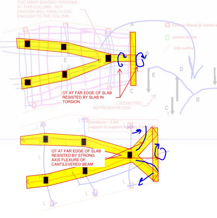
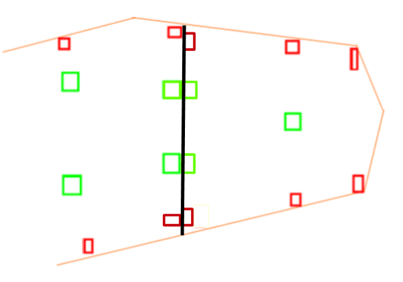
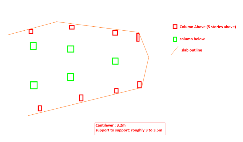
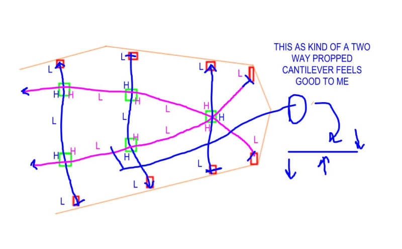
I'd also be looking hard for SOME level of redundancy if that rightmost column ever failed....outrigger-ish members in the roof (also as mentioned), a frame action from the upper floors, strength (but not deflection) from a double-bay cantilever of the left-to-right PT bands, etc.

Plenty of prominent buildings have been done recently that have overt structural cutbacks near the base (riverside in chicago, vancouver house, etc.), but IMHO these are becoming too much of a commodity, which invites our profession to speak better to the value of what we do. I would guess this is a developer-oriented architect told to maximize air rights or something, and it would surprise me if much increase in the structural fee was given. Unfortunately that arrangement puts our profession in a tough spot, stuck between the constraints of client satisfaction, technical soundness, heightened failure risk management, and of course the widespread suspicion of our profession's tendency to act as sticks in the mud. Tactfully express to the architect the challenges of this design as has been cursorily explained here; ensure you get adequate time to design it (give them early foundations as a bone); and pepper your supervisors or consultant with all these questions and anything else you feel needs attention. It is possible you (just as any of us) will discover a flaw or a mistaken assumption in your design at some future point; do your best to mitigate that risk by using all available resources now. Eng-Tips is a great supplementary resource of course; most structural companies don't have a KootK. Let's hope he doesn't start charging us!

Fun challenge though...good luck!
 
calvinandhobbes10 said:
Let's hope he doesn't start charging us!

I extract my payment in perceived good will. Although, often enough, it seems to break the other way.
 
I'd play with the idea to add a few columns and a separation joint to separate the building. The upper floor of the right side should be constructed with materials as light as possible, maybe enclosed by curtain walls. The two pars should be connected by pins without vertical load rotational capacity. The thinking is, in case of failure of the nose column, the damages could be at a minimum. Any comments and suggestions?

image_w7flde.png
 
1 You have missed the second half of my load paths for the right corner columns. Horizontal bands back to the single column line supported by the vertical support strip.

2 If the column was made stiff enough and the foundation material was able to support a fixed ended column into the foundation to take the unbalanced gravity effects and any wind and earthquake effects, then you could make it work for strength. But not with the column as shown.

3 You cannot make it robust with modified load paths within the floor. If that single column below fails for some reason, the whole 6-7m of the slab to the right of the next row of columns back has to cantilever about 6-7m. If you try to use tension ties back up through the structure and frame action, it is not just the corner columns that have to transfer back, the next row of columns also has to transfer.

A normal corner column is not a worse case as you have suggested previously as the second row of columns is in trouble in this case and it is not a single corner which can act as a double cantilever in 2 directions, the whole end is stuffed!
 
Status
Not open for further replies.

Part and Inventory Search

Sponsor