Tek-Tips is the largest IT community on the Internet today!

Members share and learn making Tek-Tips Forums the best source of peer-reviewed technical information on the Internet!

  • Congratulations TugboatEng on being selected by the Eng-Tips community for having the most helpful posts in the forums last week. Way to Go!

Beam Reinforcement Calculation 2

Nick6781

Structural
Joined
May 15, 2024
Messages
55
Location
CA
Let's say I need to use a web plate instead of a flange cover plate (I know...) to reinforce a beam. How do I calculate the required weld to ensure the section acts compositely? The shear flow equation gives the shear along a horizontal plane, but in this case, the faying surface is vertical. I can't quite wrap my head around it.


1751068113227.png
 

Attachments

  • 1751068099044.png
    1751068099044.png
    12.3 KB · Views: 5
There really shouldn't be any debate.


Try calculating the strain between the plate and the I-beam web. Compare the two. See what results you get. If the strain is equal then how is force transferred?


The side plates and I beam aren't act compositely. That is the case whether you weld the top an bottom or not. Calculate the I/Z/S values and see what you get. They are all identical whether they are composite or 'sistered' in vertical shear only. That is what the rational logic chain implies and that is what the calculation show. **

**Shear lag and any non continuous vertical shear connection will inevitably induce some shear flow but it is pretty negligible and pedantic if we really want to highlight this. For what it is worth these effects were evident in my structural analysis model presented earlier but they were about three orders of magnitude below the shear flow. AKA negligible.
Strain at the interface is also equal in the case of a bottom or top mounted cover plate.
Assume the practical case where the beam is top loaded there absolutely must be some force transfer through the welds to engage the plates, this force transfer whether vertical, horizontal or both is what ultimately induces strain in the plates providing deformation compatibility between the side plates and the beam being reinforced.

I have not fully vetted the below but this shows a 10 ft long beam top loaded with 1 kip/ft all elements are 1/4" thick A36 material
bf=8" d=12", two mid depth side plates that are 7" tall x 1/4" thick. 4" x 3/16" welds are modeled with bar elements spaced at 12" o.c.

1752156390052.png

The model indicates significant horizontal force development in the welds:
1752156503534.png

And Similar to your model fairly consistent vertical forces with skewed magnitude toward the top load:
1752156589394.png

Deformed shape which appears consistent to what I would expect to see:
1752156685831.png
 
That does not make sense to me. You may want to add welds at the ends of the plates to transfer the load back out into the I-beam web (can't tell if they exist or not).
 
I have mostly read earlier posts. Couple comments not related to each other:

@human909 - You said a few times that Q=0 at centroid. Q=A*y. Q is maximum at centroid. Q=0 at top/bot edges because A=0. Q=0 for whole section because y=0 by definition but not what people mean when they say Q at centroid.

@BAretired - Don't need welds top and bottom of plates from original question to carry longitudinal shear. No difference in strain compared to main section as others said so no stress develops in welds. You could do plug welds anywhere within plate area instead. Consider welding a tee on top of I-beam. You can only weld bottom of tee. Lack of weld at top no issue. Same way could weld just one edge of plates and get composite action even if offset plates from neutral axis so have longitudinal shear in weld. But welding top and bottom will also work of course.

General comment on physical meaning of Q: Foot in both camps. Agree with Human909 that Q is geometric parameter because only need geometry to calculate it. But also agree with BAretired that Q is only used in elastic calculations. Q=A*y represents force when you have linear stress gradient like elastic conditions. Parameter y represents stress because stress is proportional to distance from neutral axis = centroid for pure bending. Doesn't work for plastic stress profile, or cracked concrete as another example.

Shear flow is change of force over length. Calculate Q for the part of cross section you want to know change of force for. No need to subdivide plates like BAretired is doing because one weld is enough as per above.
 
XR250, Yeah, that looks like the first edition, all I can find online as to traces is an arabic translation from 1981, so probably. Abebooks normally has this information but not for this book. Yeah, I know, not the question being asked, but....

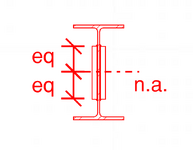
Fundamentally this is a built-up shape.

Since Koot is absent, since we are kind of presuming this reinforcement is for bending, there's a shear flow into and out of the element (top and bottom) of the side plate. Q is determined on the height of the element, so at the top of the added plate and the bottom of the added plate. For normal bending this should produce the same shear flow requirement. If it isn't adequately welded to transfer the shear flow, the element won't absorb any stress or provide any benefit. The welding spacing (if intermittent) should also be checked to ensure the plate doesn't buckle (in bending) between the welds, but for normal welds and plates this probably won't control.

Anybody looking for a better understanding of Q, or actual shear in beams versus how we simplify the design via a simplified check, should look at ... (hang on.... Steel Structures, Design and Behaviour, Wang and Salmon, third edition, or later. Section 7.7 Shear on Rolled Beams.

Sorry I haven't read the five pages of discussion, so if somebody already referenced this, I'm being repetitive.
 
The example in my Timoshenko book is similar to what Celt posted and even calls it "horizontal shear force". The outstanding plates are forced to act compositely with the combined section. I don't know the practical use of all this other debate and haven't read all of it.
 
I am going to go back to my previous argument. If the moment of inertia of the combined section is the same as the sum of the inertias of the individual elements, how can there be any horizontal shear between them?
 
There really shouldn't be any debate.


Try calculating the strain between the plate and the I-beam web. Compare the two. See what results you get. If the strain is equal then how is force transferred?


The side plates and I beam aren't act compositely. That is the case whether you weld the top an bottom or not. Calculate the I/Z/S values and see what you get. They are all identical whether they are composite or 'sistered' in vertical shear only. That is what the rational logic chain implies and that is what the calculation show. **
If the beam is loaded from the top flange of the beam, and the plates are at the centroid of the beam, then how does any load get into those plates unless you size it for the shear flow at the location of the weld? Beam starts to deflect and for the plates to be engaged they need to bend with the beam.
 
The sketch below shows a beam cross section with a bulge in the middle, i.e. all one piece.
No need for any welds, but the horizontal and vertical shear at several points is calculated using VQ/Ib.

If instead of a bulge, we use two side plates, why should it be different, other than the fact that we need welds in the case of side plates?


1752177905454.png
 
Last edited:
1752178546689.png
Source: Stack exchange.

Where the section changes, shear jumps. If this were a plate girder you'd be welding the top and bottom plates to the web to transfer that shear, it's no different than the case at hand, it's just the section is getting thicker in the middle which is atypical. If it isn't properly welded either it shears off when the welds fail, or it doesn't contribute some other way.

We "model" shear as rectangular and only in the web because it's 97% accurate and the procedure dates from the 1960s, (and there's a factor of safety) so it's uh, slide rule friendly. Most rolled steel beams are also compact so they endure minor deviations...
 
@lexpatrie , you really need to read the rest of the thread. You are missing the point. All the points you are making have already been made, but they do not satisfactorily resolve the the ongoing debate.
 
The example in my Timoshenko book is similar to what Celt posted and even calls it "horizontal shear force". The outstanding plates are forced to act compositely with the combined section. I don't know the practical use of all this other debate and haven't read all of it.
I think the practical use is to understand how shear flow works in unusual situations. Not many engineers would reinforce an I-beam with short side plates, but if they did, we could calculate the shear stress at any point. And from that, we could calculate the welds required to adequately engage the reinforcement.
 
I think the practical use is to understand how shear flow works in unusual situations. Not many engineers would reinforce a beam with short side plates, but if they did, we could calculate the shear stress at any point. And from that, we could calculate the welds required to adequately engage the reinforcement.
@BAretired , what about the fact that, in this case of side plates positioned symmetrically about the neutral axis, the same total (not composite) resistance to bending could be obtained by installing through bolts or dowels through all three pieces at the the common neutral axis, or for that matter by installing dowels through just the I-beam web directly above the side plates? What effect does this have on your shear flow argument?

Forgive me if you have already addressed my question elsewhere. I am doing my best to keep up with this thread.
 
I have mostly read earlier posts. Couple comments not related to each other:

@human909 - You said a few times that Q=0 at centroid. Q=A*y. Q is maximum at centroid. Q=0 at top/bot edges because A=0. Q=0 for whole section because y=0 by definition but not what people mean when they say Q at centroid.
Q at the neutral axis is not 0, I agree. Q is the area above or below the section where shear is to be found and y is the distance of its c.g. to the n.a.
@BAretired - Don't need welds top and bottom of plates from original question to carry longitudinal shear. No difference in strain compared to main section as others said so no stress develops in welds. You could do plug welds anywhere within plate area instead. Consider welding a tee on top of I-beam. You can only weld bottom of tee. Lack of weld at top no issue. Same way could weld just one edge of plates and get composite action even if offset plates from neutral axis so have longitudinal shear in weld. But welding top and bottom will also work of course.
Sorry, but weld on one edge is not enough to properly engage the side plates.
General comment on physical meaning of Q: Foot in both camps. Agree with Human909 that Q is geometric parameter because only need geometry to calculate it. But also agree with BAretired that Q is only used in elastic calculations. Q=A*y represents force when you have linear stress gradient like elastic conditions. Parameter y represents stress because stress is proportional to distance from neutral axis = centroid for pure bending. Doesn't work for plastic stress profile, or cracked concrete as another example.
I also agree that Q is a geometric parameter, but it applies specifically to a member in the elastic state. I have not worked out the expression applying to a member fully or partially in the plastic state.
Shear flow is change of force over length. Calculate Q for the part of cross section you want to know change of force for. No need to subdivide plates like BAretired is doing because one weld is enough as per above.
Sorry, but you are mistaken about that. The weld on top resists a force equal but opposite to the weld on the bottom of the side plate. Both welds are needed, one resisting a force into the page, the other resisting a force out of the page. Of course the vector sum of the two forces is zero.
 

Part and Inventory Search

Sponsor

Back
Top