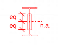
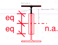
I agree with this 100% this approach to the calculation IF we were trying to calculate the shear requirements of fixing that top T to the rest of the assembly. And my next step check whether that web is strong enough to transfer the shear which it is. Hence no welds required to transfer
It has been calculated. And that calculation has been denied. It has been explained in a dozen different ways using logic and that has been ignored. I've tried pointing to the other thread.
What matters here is that if in the absence of a connection there would be a discontinuity in the stress gradients. This discontinuity needs to be resolved if there was going to composite behaviour.
But in the case of members that have a common centroid there is no discontinuity in the stress gradients if they are simple 'sistered' together. stress and strain are identical. Thus there is no discontinuity.
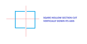
YET ANOTHER EXAMPLE:
Consider a Square hollow section cut down its axis and calculate the shear and the weld required. Using VQ/I in the major axis we wouldn't required any weld as the resistance to bending is unchanged. The calculation unsurprisingly yields a ZERO result. Though calculate it for the minor axis and you have a completely difference result, again as expected. You'll find yourself needing to weld that cut back up to restore the strength stiffness in the minor direction.
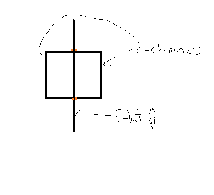
View attachment 14778