Continue to Site

Eng-Tips is the largest engineering community on the Internet

Intelligent Work Forums for Engineering Professionals

  • Congratulations waross on being selected by the Eng-Tips community for having the most helpful posts in the forums last week. Way to Go!

Beam Over Column Connection 1

Status
Not open for further replies.

Veer007

Civil/Environmental
Sep 7, 2016
379
Hey Guys,

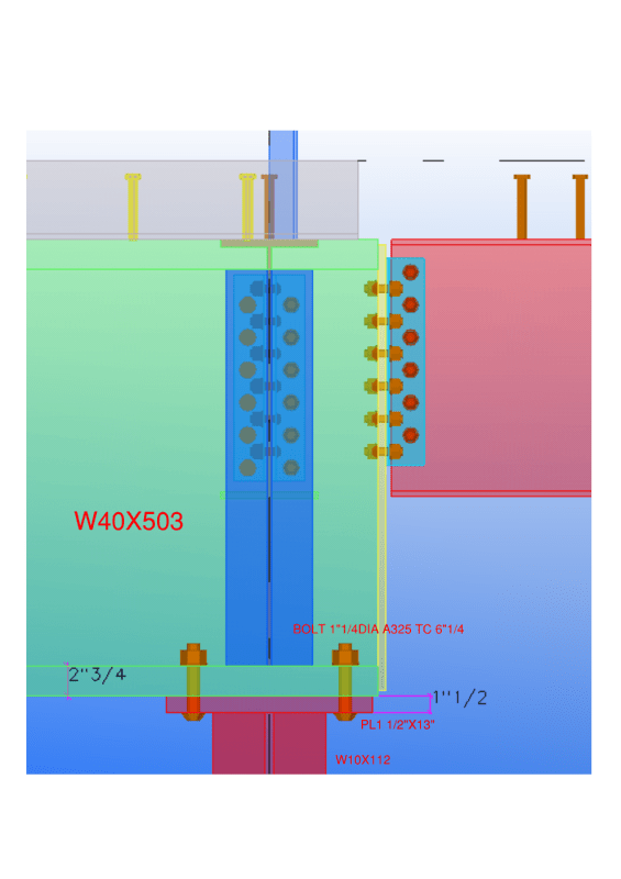
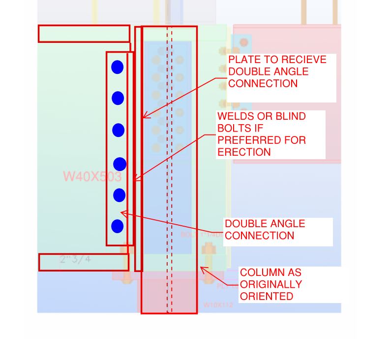
I have the case, where beam bearing on column cap plate which has 360kips as shear and no moment force. Shear force will be satisfied by using direct bearing. Is this necessary to design cap plate thickness and number of bolts still? If yes any way to design? Or just I need to provide cap plate thickness same as beam flange?

below from AISC (Hollow StructuralSection Connections) states cap plate thickness should be min of beam flange.

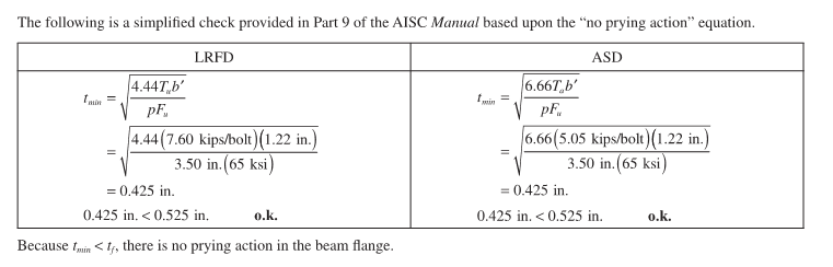
[highlight #EF2929]"The following is a simplified check provided in Part 9 of the AISC Manual based upon the “no prying action” equation.
Because tmin < tf , there is no prying action in the beam flange."[/highlight]

Capture_s3kkeb.png


Beam flange thickness is 2.75"

Document1_l16pij.png


Thanks in advance!!
 
Replies continue below

Recommended for you

I think that you're at a crossroad here where you ought to do one of two things:

1) Synthesize all of the excellent information that you've been provided here and use your own judgement as to how you'd like to proceed AND/OR;

2) Pick your favorite connection, decide if you want to design it as pinned or rigid, and run that assumption past the EOR for review, letting her know about your concerns.

OP said:
I forgot to give some info that column height is 12 feet and beam length is 50 feet

Your column height is half what Human909 and I were working with and, therefore, will be considerably stiffer. That will, of course, impact the results.

Human909 said:
I now agree with this conclusion.

Consensus!! That is both rare and awesome. Thanks for reporting back with the updated.
 
007 said:
BA[/color]]calm after a storm, After so many replies, What I understand is for this larger beam if the connection will be designed as pinned, it will allow some rotations so that there is no effect on the column. Also, we know all pinned connection is are not completely pin, it will act as slightly rigid too. right?
Sounds about right to me.

I forgot to give some info that column height is 12 feet and beam length is 50 feet.
That is helpful information. Column height is 3.65m. A W10x112 is W250x167.
Assuming G40.12, ASTM A992, A 572 grade 50. At KL = 3.75m, Cr = 5070kN. Mrx = 755kN-m. Mry = 354kN-m.
I don't have much knowledge about design main members like columns and beams, but it's my responsibility to design connections. Understood!

So you guys recommending to rotate column, so that it will arrest moment on its major axis while now column located transverse to beam web, is it?
The only reason to rotate the column is to create a better detail where the column extends up and the beams connect to the flanges instead of sitting atop the column. If you do not agree, don't do it as it appears the column is more than adequate as shown.

So finally can I go with the Kootk solution? as adding stiffener. But Still, it's required if we designed this as pinned?
It is not necessary to design as pinned. The beams can be rigidly connected to the column and the connection can be accepted as somewhere between fixed and pinned. It simply doesn't matter.

BA
 
Circling back to the original question:

1) The detail that I proposed essentially bypasses the cap plate and, therefore, obviates the need to check anything there other than the reasonableness of proportions, at least as far as downwards, gravity load is concerned.

2) OP's original detail also does a fine job of bypassing the cap plate so long as the WT stiffeners are set up properly. I assume this was the reason for the use of WT stiffeners in the first place. I think my detail is a bit cheaper to fabricate and more conventional but, then, who doesn't prefer their own details?

As shown below, there is a fairly simple way to facilitate the use of a clip angle connection without modifying the column orientation. This setup does indeed have some advantages; reducing incidental column moment simply isn't going to be one of them in many practical situations.

C01_pdttlx.jpg
 
Kootk solution looks fine... But the beam at the other end cantilevers about 4'-0".

Thanks in advance!!
 
Veer007 said:
Kootk solution looks fine... But the beam at the other end cantilevers about 4'-0".
Wow! Now that is a plot twist I didn't expect! [borg2]

That really changes EVERYTHING about the previous discussion. You really know how to string us along Vee007 to suck us into the second season. That connection needs some serious work other that crowdsourcing your answers.
 
Yeah, the cantilever bit will tend to steer the preferred solution towards either:

1) Beam over column or, at least;

2) Rotating that column 90 deg if the column could take the bending from the short cantilever.

C01_gdgsum.jpg
 
Out of curiosity, I did a 30 minute science experiment based on this thread and another thread referenced above by KootK (I'm not sure I'm trying to prove anything, but I think it's fun and entertaining to do things like this.

This compares a flimsy column to a rigid column.
The beams over the columns are W8×31's.
Moment connection exists between beams and columns.
Nodes at bases of columns and right end of beams are pinned.
40 kip load at the left end of each cantilever.

Experiment_sltr1y.png
 
That is fun.

What modeling software are you using?

Elastic, second order analysis?

What's your takeaway?

It appears that the rigid column is effectively making the beam back span non-participatory. Basically a short cantilever with fixed support.
 
Veer007,

You should confirm the design loads with whomever is responsible prior to conclude your design. Things don't add up.
 
Hey Guys, This is a full snap. The cantilever beam is not a pink one, its another end about 5'-0"
Capture_o7kvqc.png


Thanks in advance!!
 
You need moment connection at the joint, don't you?
 
You need moment connection at the joint, don't you?
Why? Deeper beam cantilevers over column. Other end (pink beam) is not a cantilever as explained?
 
My negligence. I was stare at the original joint thinking a 5' cantilever in the transverse direction.
 
KootK said:
That is fun. What modeling software are you using? Elastic, second order analysis? What's your takeaway?

Hey, we're only in it for the fun right? And maybe the money sometimes.

I did this in RAM Elements, marked it up in Foxit Reader, and mastered it in MS Paint.

I re-ran it with a second-order analysis (P-delta), it failed to solve and spit out an instability error having to do with rotation about the bases of the flimsy columns. I fixed the column bases and produced the image below. I also ran it with the tops of the columns pinned, and I might run it again after factoring in some displacement based on columns that aren't quite plumb. I'd also like to re-run it with code checks and figure out how it all compares if I ensure that the stress ratios meet code.

In terms of takeaways, it seems ideal to treat the connection and maybe the column as being fixed, and to treat the beam and maybe the column again as being pinned. But it's probably more gray than black and white, How to treat the column might depend on how big the load is, and the decision as to which is the "validest" probably has a lot to do with the rigidity of the connections/beams, the nodal stiffness and the magnitude of the load. A pinned cap plate on a maintenance platform should work all day. But if I'm not mistaken, treating shoring posts as pins might have contributed to the collapse of the Hard Rock Hotel. Or maybe they just needed more of em. Or maybe they should have been beefier.

My gut tells me that a (4) bolt cap plate where the bolts exist beyond the neutral axis should likely be regarded as a fixed connection. Given a column that's sufficiently stiff, but maybe not so stiff that it would cripple the web of the beam, the force at the end of the cantilevered portion of the beam should cause the beam to pivot about on the edge of the cap plate. That rotation would be resisted by the opposite pair of bolts, thus creating a force couple.

I wonder how it would work if I turned the pin on the right side into a big shock absorber...

Fixed_vs_Pinned_anb3tu.png
 
My main concern on this system is the rotation about the longitudinal beam axis. But there must be transverse beams that help to stabilized the large beam. The remaining puzzle to me is the lack of horizontal shear force, or the consideration of it.
 
r13,
The large beam is presumably braced to resist torsion at each of the supporting columns.
Where is the horizontal shear force which puzzles you? I don't see it.

BA
 
BA,

Please read my response again. Thanks.
 
r13,

Instead of coming up with useless comment, explain what horizontal shear you are talking about.

BA
 
r13 said:
The remaining puzzle to me is the lack of horizontal shear force, or the consideration of it.

It is a question to the EOR, or the designer, as it is inconceivable that a framing system having zero horizontal shear force. As a contract connection designer, I don't have the obligation to, but I would chose to advance my concern to whomever provided the design information. I hope this question is not deemed "useless" in helping the OP for his professional behalf.
 
BAretired,

You never know when a horizontal force will present itself. I once designed a pipe rack and neglected to brace it out of plane. During a walkthrough, the client grabbed the top of the pipe rack and shook the bejesus out of it back and forth. While he shook it, he asked why there wasn't any bracing, I told him I didn't expect any out of plane horizontal force. He said "that doesn't matter, it's the standard."


ra13,

Are you talking about this in context of the beam acting as a roof girder? And the transverse beams being purlins? In terms of horizontal shear, you're talking about wind on a roof? Or maybe an earthquake on a floor?

In my images above, I imagine this setup could be a picking beam with a manual hoist/trolley located inside the basement of a building. In that case, I'm not sure what lateral forces you would need to consider
 
Status
Not open for further replies.

Part and Inventory Search

Sponsor