Continue to Site

Eng-Tips is the largest engineering community on the Internet

Intelligent Work Forums for Engineering Professionals

  • Congratulations waross on being selected by the Eng-Tips community for having the most helpful posts in the forums last week. Way to Go!

Beam Over Column Connection 1

Status
Not open for further replies.

Veer007

Civil/Environmental
Sep 7, 2016
379
Hey Guys,

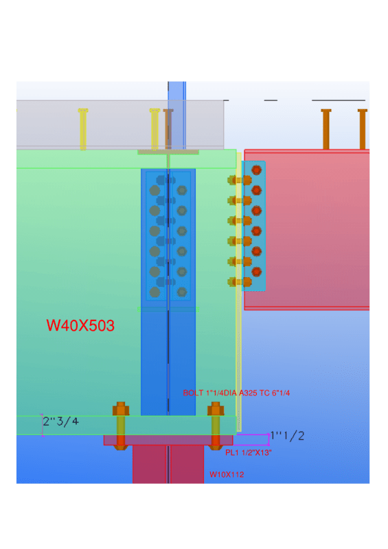
I have the case, where beam bearing on column cap plate which has 360kips as shear and no moment force. Shear force will be satisfied by using direct bearing. Is this necessary to design cap plate thickness and number of bolts still? If yes any way to design? Or just I need to provide cap plate thickness same as beam flange?

below from AISC (Hollow StructuralSection Connections) states cap plate thickness should be min of beam flange.

[highlight #EF2929]"The following is a simplified check provided in Part 9 of the AISC Manual based upon the “no prying action” equation.
Because tmin < tf , there is no prying action in the beam flange."[/highlight]

Capture_s3kkeb.png


Beam flange thickness is 2.75"

Document1_l16pij.png


Thanks in advance!!
 
Replies continue below

Recommended for you

what about the pink painted beam ( could be W 24..? ). said:
It's W24X55

I guess your task is to provide details for the connection said:

Did you consider the stability of beam W 40 X 503 during erection? said:
At the blue color wt stiffener supports W24X76 beam which helps stability of beam

Did you consider minimum eccentricity in the design? said:
I didn't think so as load will be transferred through center of column

Is it necessary to consider column weak axis? Doesn't column axial compression capacity enough?

Thanks in advance!!
 
Veer007 said:
I didn't think so as load will be transferred through center of column
This assumption is not congruent with your pinned connection assumption.

(A pinned connection implies some rotation of the beam of the end of the beam which implies unequal load distribution on the cap plate.)
 
As I believe human909 might of mentioned earlier, the column axial load should be considered acting at the edge of the column in line with the beam axis.

This requirement is due to the inherent tolerance on welding the end plate to exactly match the slope of the underside of the beam, and corresponding rotation of the end of the beam. This results in the beam possibly sitting like a knife edge at the column edge.

This condition is called out explicitly in the codes in this part of the world as requiring consideration. No idea if AISC also cover something similar.
 

I have also done both ways..but I used continuous construction with the beam running over the column if the beams are the same size . If different size of beams more than two , i preferred to extend the column.


The column weak axis will experience more moment than the column axial load is considered acting at the edge of the column. Just make a simple calculation.. Assume the beam W 40 X 503 simply supported and find the rotation at support. This rotation could be assumed for calculation of column moement for weak axis.

IMO, stability of W 40 X 503 is a concern during erection and the cost is higher for this type of connection.
 
Veer007,

Alright then. The Q&A below, excerpted from the Steel Interchange article, seems suggest the eccentricity can be ignored. Link

Eccentricity on Columns
Q. Are there any formal recommendations concerning the inclusion of eccentric moment in a steel column due to
the physical distance between the beam end and column centerline?

A. The decision to account for the eccentricity or neglect it is one that you have to make based on your engineering
judgment. Ioannides (“Minimum Eccentricity for Simple Columns,” ASCE Structures Congress Proceedings, Volume
1, 1995) suggests that even for a column that is loaded on one side only, the restraint a connection provides to the
column will help mitigate the eccentric effects in normal framing configurations.
 
r13 said:
Veer007,

Alright then. The Q&A below, excerpted from the Steel Interchange article, seems suggest the eccentricity can be ignored. Link

Eccentricity on Columns
Q. Are there any formal recommendations concerning the inclusion of eccentric moment in a steel column due to
the physical distance between the beam end and column centerline?

A. The decision to account for the eccentricity or neglect it is one that you have to make based on your engineering
judgment. Ioannides (“Minimum Eccentricity for Simple Columns,” ASCE Structures Congress Proceedings, Volume
1, 1995) suggests that even for a column that is loaded on one side only, the restraint a connection provides to the
column will help mitigate the eccentric effects in normal framing configurations.
That is a great example of engineering doublethink. If there is enough restraint to mitigate eccentric effects then you you must be transferring moment. If you aren't transferring moment and it is a pinned connection the eccentricity is expected to occur about the centroid of that pin support. (The edge of the cap plate is conservative.)

Like I said much earlier if you make your cap plate much smaller and brine your bolts in closer to the center-line then you will get a behavior that is more pin like.
 
For what it is worth whether you account for every bit of eccentricity in you structure is a judgment that needs to be made as an engineer. Personally I don't usually factor it into my designs unless I foresee it being an issue. That said for the sake of the exercise I just manually modified a design I am finish up to include eccentric column connections. The 310UC137 (approximately a W 12 x 87) column experienced a 13% loss in capacity under ultimate limit state (1.2G+1.5Q). For the sake of expediency I prefer to keep my design loads a healthy margin under my design limits. That healthy margin is normally least 20% but generally around 30%.
 

I didn't get this point, if cap plate smaller than beam flange and bolt near to Centre of beam web, it will be pinned connection?

But larger cap plate and larger bolt spacing act as rigid connection?

rigid connection better than pin, right? please make me clear


Thanks in advance!!
 
Veer007. I'm not sure you are recognizing the subtle point that almost no connection is fully pinned or fully rigid. There is plenty online to read, here is one example:

Veer007 said:
I didn't get this point, if cap plate smaller than beam flange and bolt near to Centre of beam web, it will be pinned connection?
It will behave in a less rigid and more flexible fashion. At minimum you should be bringing the bolts completely inside the flanges. To get it to 'closely' behave like a rigid connection you should be keeping the cap plate as narrow as possible and very close bolts

Veer007 said:
But larger cap plate and larger bolt spacing act as rigid connection?
A large thick cap plate with wider bolts would behave fashion that closely approximates a rigid connection. Some/many codes have pretty onerous strength requirements for rigid connections. So it will often mean many bolts, thick plates (flange doublers, web doublers, etc...)

Veer007 said:
rigid connection better than pin, right? please make me clear
If you can't answer this question yourself you need to do more reading and self education. Short answer is they are both important in design and the wrong sort of connection could potentially have disastrous results.


But like MANY people here have said. Make your life easier, extend the column and use angles or a cleat. Preferably discuss rotating that column 90degrees as the eccentricity of a flange connection is likely unideal given the differences in size between the beam and the column.
 
okay human909, I'll try to change this as pinned connection..

Thanks in advance!!
 
That is a very rigid joint there kookt. Given that the original engineer called upon a pinned connection that seems quite an unconservative approach without knowing more detail. Yes the W40 is very stiff, but for all we know it could be quite a long span with a non insignificant curvature at this end. If this curvature isn't allowed by a pinned connection it will be induced in the column with a transfer of moment.
 
human909 said:
That is a very rigid joint there kookt.

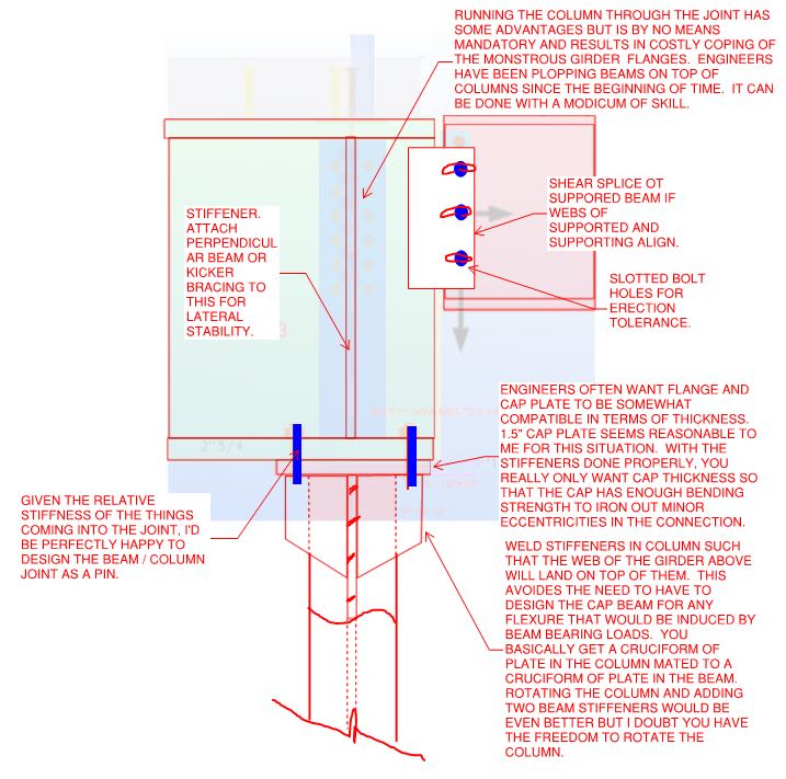
The key to this, and most situations like it, is to realize that [JOINT RIGIDY <> ATTRACTION OF SIGNIFICANT MOMENT]. Most "pinned" joints are, in fact, quite rigid. As we've discussed several times in the past, it is my firm belief that well in excess of 90% of North American structural engineers would be comfortable calling this a pinned joint.

human909 said:
Yes the W40 is very stiff, but for all we know it could be quite a long span with a non insignificant curvature at this end.

Sure, if the beam is 200' long and the column 6' tall, that's another story. But, then, that's an OP problem and precisely why he has a brain of his own. I see no need to let fear over extreme situations hinder the dispensation of good advice that would be applicable to most practical situations.

Another party here who's probably a smarty is the engineer of record. Show them the connection and see what they think.
 
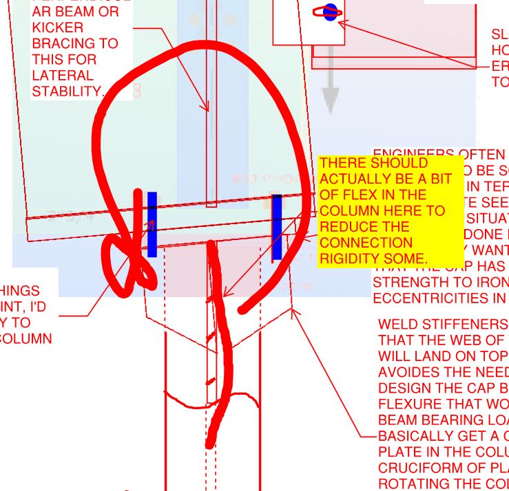
There's also a mechanism of flexibility at the column stiffeners that would tend to soften the joint a bit where it matters most (under the beam web).

C01_mrszmz.jpg
 
KootK said:
The key to this, and most situations like it, is to realize that [JOINT RIGIDY <> ATTRACTION OF SIGNIFICANT MOMENT]. Most "pinned" joints are, in fact, quite rigid. As we've discussed several times in the past, it is my firm belief that well in excess of 90% of North American structural engineers would be comfortable calling this a pinned joint.
I would be interested in a survey to prove this assertion. Pretty much all engineers I've met and all North American literature I've read would be describing that as a ridged or at the very least a semi-rigid connection.

KootK said:
Most "pinned" joints are, in fact, quite rigid. As we've discussed several times in the past, it is my firm belief that well in excess of 90% of North American structural engineers would be comfortable calling this a pinned joint.
Depends what you mean by quite and depends whether you are talking under light loaded or under ultimate loads.

There is plenty of research on this that shows connection behavior including semi-rigid connection which is the awkward in-between and more difficult to predict.


Pick a couple of reasonable lengths for these members or better yet if the OP can provide. I'll see if I can model it to determine the expected stiffness. I agree that there would be some flex as shown. But as also shown you are getting a fair bit of moment transfer. Like I said at the very least this would fall into the semi rigid zone.
 
human909 said:
Pretty much all engineers I've met and all North American literature I've read would be describing that as a ridged or at the very least a semi-rigid connection.

But again, [JOINT RIGIDY <> ATTRACTION OF SIGNIFICANT MOMENT]. My assertion is not that the joint is flexible. Rather, my assertion is that in many practical situations, a rigid joint will not draw significant moment to the connection. It's the same thing as how we often call truss web connections pinned when, in fact, most of them are quite rigid under conventional detailing schemes.
 
Some other feature of the situation that, in my mind, help to justify a pinned design assumption:

1) EOR probably designed the column as K=1.0. To the extent that the joint is rigid, K -> 0.7 ish.

2) Whatever moment is attracted to the joint will be self limiting. Basically, at worst, the curvature at the to of the column will match the curvature at the end of the beam if the beam were designed not considering any end restraint.

3) Any incidental moment will be column weak axis moment. Therefore, there is no LTB potential and the top of the column may well be able to yield its way into being a hinge if it had to.
 
We did some related work recently in this thread for anyone who might be interested: Link
 
kootk said:
Some other feature of the situation that, in my mind, help to justify a pinned design assumption:

1) EOR probably designed the column as K=1.0. To the extent that the joint is rigid, K -> 0.7 ish.

2) Whatever moment is attracted to the joint will be self limiting. Basically, at worst, the curvature at the to of the column will match the curvature at the end of the beam if the beam were designed not considering any end restraint.

3) Any incidental moment will be column weak axis moment. Therefore, there is no LTB potential and the top of the column may well be able to yield its way into being a hinge if it had to.
They are all good justifications on why the connection you design may not result in a worse outcome from a strength perspective. They aren't justifications to argue it is a pinned connection.

Like I have said before. I've see this type of connection design go wrong in such a way that the column underneath was visibly bending like a banana due to the induced moment. The EOR had designed the connection as a pinned connection but the actual connection was a cap plate with bolts outside the flange. Likewise the depth of the beam was 3-4x the depth of the column. This was a problem that needed to be rectified and it was caused by a connection modelled as a pin but designed and behaving like a rigid connection.
 
KootK said:
2) Whatever moment is attracted to the joint will be self limiting. Basically, at worst, the curvature at the to of the column will match the curvature at the end of the beam if the beam were designed not considering any end restraint.

I think I agree with the intent of the above, but would change the word curvature to slope. For the column, the slope at the top determines the moment. For the monster beam, the moment is negligible.

BA
 
Status
Not open for further replies.

Part and Inventory Search

Sponsor