Continue to Site

Eng-Tips is the largest engineering community on the Internet

Intelligent Work Forums for Engineering Professionals

  • Congratulations cowski on being selected by the Eng-Tips community for having the most helpful posts in the forums last week. Way to Go!

About Piping Welding, Calculations and Codes 5

Status
Not open for further replies.

Gabrielsfe

Mechanical
Mar 10, 2017
12
Dear colleagues:

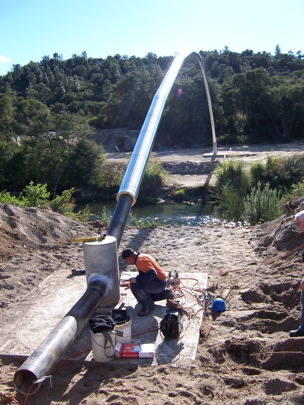
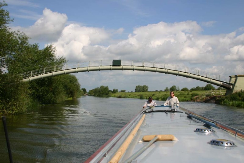
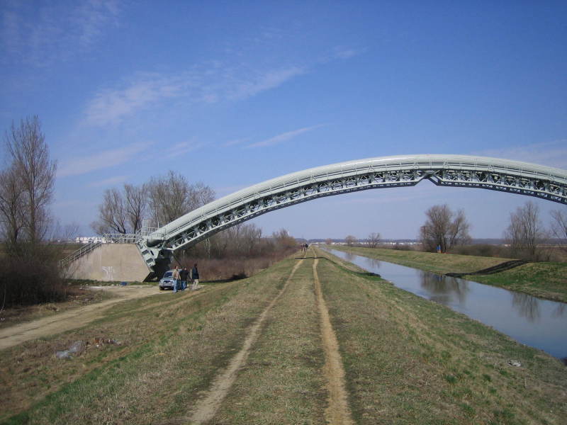
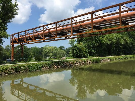
I m working in a project where I have to design a water piping system DN 900 using "curved" metal Sheets ( I'm not sure if "curved" is the correct word in English).

I have an issue:

I don't know which is the a code or standard that indicates me the way to calculate and design the longitudinal seam and the seam between two consecutive tubes. Where is the formula/e?. I must do a Calculation Report indicating the formula, allowable stresses, safety coeficients, etc., and the source of the data, etc.


Thanks

I would appreciate your help.

PD 1: The specifications say I have to use AWWA Codes ( they doesn't help too much...)

PD 2: I have access to ASME Code VIII Div 1 Rules for Construction of Pressure Vessels but one paragraph says that this code doesn't apply for piping...
 
Replies continue below

Recommended for you

The latest drawing is a plan view of the total pipe run which is to be made from 1500mm long sections fabricated from "welded curved steel plates", I presume?
 
Your file won't download - I think there are some strange characters in the name. Just store it as data.pdf and upload that...

I think what you're asking for is what is the joint factor applicable for longitudinal welded pipe?

Depends on which design code you're using. B 31.3 didn't like longitudinal pipe so applied a 0.8 factor on the wall thickness

If it's AWWA then I don't have much experience of that - It looks to me like you need a copy of AWWA Manual M11
Apply the code that the client has told you to.

Remember - More details = better answers
Also: If you get a response it's polite to respond to it.
 
Comment for Gator: Yes, you are right. The total pipe run is to be made from 1500mm long sections fabricated from "welded curved steel plates.

Comment for LittleInch: I have attached the file in PDF version with new name DATA.
Maybe I didn't explain very well. What I looking for if is there a Code or Standard that indicates how to verify the Longitudinal Seam to form a tube from curved steel plates.

In other words: must be exist a method/code/standard that indicates,with no doubts, the way to calculate/verify this type of weldings: the allowable stress to be adopt, the theory of rupture used, the Safety or reduction coefficients, etc., with a given plate material and a given internal pressure ( B31.3 make mention of how to calculate the pipe thickness, but there is no information or guidance about Longitudinal weldings).

AWWA: with regards to AWWA, the specific AWWA 206-97 FIELD WELDING OF STEEL WATER PIPE says:"...The design of field-welded joints is not covered...."
PD: Someone has a copy of M11 Steel Pipe -- A Guide for Design and Installation, Fourth Edition (PDF)?
 
 http://files.engineering.com/getfile.aspx?folder=1f7b2d6a-20c8-4455-bbfb-79f68cd9d09b&file=DATA.pdf
I'm going to give you my honest and unvarnished assessment of this entire situation. There is so so much more to this type of design than the simple question that you are asking. On the basis of your questions asked and not asked, and your replies provided already, you are grossly unqualified to perform this work. If you cannot back out of this work, then please hire someone who is qualified. You will not be able to learn your way out of this situation - it's just much too complicated. Most of us have spent a lifetime learning this, mostly learning from mentors who also have a lifetime of experience.
 
I kind of agree with my fellow posters that you appear to be getting involved in something well outside your current experience range without adequate help and assistance. There is only so much an internet forum can do.

I am knod of fascinated with this post as it is one of the strange rones to appear.

Your drawing, which finally downloaded, appears to show a curved pipe ( not sure if this is horizontal or vertical, but never mind) made up of multiple short lengths of pipe, presumably your 1.5 m lengths of 900mm ND welded at what I can only assume is some sort of mitre bend??

Now how and why you have arrived at this design is beyond me and maybe you can fill us in on this.

The multiple welds, both axially and girth welds would seem to make this very expensive and if you are actually trying to make this pipe, it strikes me more like someone trying to build a car based on buying all the spare parts. Some one once calculated that to do it this way made a $15,000 car cost $150,000....

In answer to you question I have attached a brochure from a steel mill which explains the process. It also has a list of pipe specifications in the back including AWWA C200 which I think is your best point of call.

Normally seam welded pipes ( there are multiple ways you can weld the seam) are examined by UT and sometimes X ray depending on the specification and the purchasers (i.e. you) specification.

Allowable stress and safety factors are determined by the code you are working to, hence you need to obtain (purchase) a copy of the code. They vary from 0.72 to 0.5 generally over SMYS (min yield stress).

Theory of rupture I don't understand, but Barlows hoop stress formula is used in all pipeline codes I've ever seen.

So can you come clean here and advise what the design conditions are:

Fluid - water?
Design pressure?
Material of this curved plate
Wall thickness you intend to use
Type of seam weld you intend to use
Why you're not buying ready made pipe from a supplier and then bend it?
what this mysterious curved pipe is all about

Good luck

Remember - More details = better answers
Also: If you get a response it's polite to respond to it.
 
 http://files.engineering.com/getfile.aspx?folder=61385c61-2020-4c4f-8dd5-1bd9f592f720&file=welded_line_pipe.pdf
TGS4: Thank you for your advice. Specifically for this work I will look for some external help.
The subject about large diameter piping system has resulted very interesting to me and I think I will continue researching about it. Thanks.
 
LittleInch: Your post has information very useful to me.
Despite of I will look for external assistance I will answer the questions of the last paragraph.
Fluid: water
Design pressure: 10 BAR
Material of this curved plate: A53
Wall thickness you intend to use: 1/4"
Type of seam weld you intend to use, full penetration according to AWWA 200 or B31.1
Why you're not buying ready made pipe from a supplier and then bend it? We assume that a 900 mm ND pipe and thickness wall of 6.4 mm can't be bended as the curve showing in the drawing without dangrous deformations or due to the buyed pipe lenght of abot 12 meters or more the "bending" process will be too expensive.
what this mysterious curved pipe is all about: is a part of a larger piping network. The curve is to cross a little river.
 

That's a pretty thin pipe (D/t of 141??). I'm not sure how you were planning on getting the pipe below? the river, but I would have used some formed bends of a thicker material to get the angles and the y just used some straight bits of pipe.

You might also have significant forces on the pipe from soil and other loads.

One thing I forgot - Keeping the pipe within some very strict ovality limits as you make it will be very very difficult. At that thickness of material, any ovality will mean your pipe edges won't match up to weld them and any force to clamp them together would just buckle the pipe.

Remember - More details = better answers
Also: If you get a response it's polite to respond to it.
 
You will need some structure to support the weight of the pipeline (empty), the pipeline + water and the cross-wind load.

Taking advantage of the natural catenary curve that the pipeline assumes under its own weight, you could save some welding by using longer sections.

Will you also manufacture the straight and curved pipes that will connect with this bridge?

Please, follow this link:

AAEAAQAAAAAAAAitAAAAJDE2OWFhYjBiLTJlYzMtNDdmYS04M2JmLTUxMTdjYWViMTliNQ.jpg


"Engineering is achieving function while avoiding failure." - Henry Petroski
 
The OP of course referred to the eventually readable attachment as a "plan view" of an apparently horizontal curved pipeline path, consisting of apparently short mitered 60-inch pipe segments. It was explained later, "The curve is to cross a little river". I furthermore thought I could see some on this plan joints apparently drawn as flanged (and read the Spanish word "brida" on the plans, I believe referring to such).
Irrespective of the wisdom of trying to learn on such a job how to manufacture, coat and line, and handle seemingly from scratch all other nuances of large diameter steel piping supply on such a job, unless this piping is required to closely follow the contours of a bridge (neither pictured nor noted) horizontally curved for some unknown reason, this appears to be a quite inefficient in material and labor, and perhaps also risky way to run a large pipeline across a river. This inquiry at the very least begs for some more information to be supplied

 
Comments to LittleInch, Lnewqban and rconner
The drawing I've attached with short mitered 60-inch (1500 mm) pipe segments is a preliminar idea or design that the client proposed. The way to form the curve layout can be changed according to the availability of material, materials costs, labour costs, new desig, manufacturing labour, assembly methods on site, e.g. using some formed bends of a thicker material to get the angles and some straight bits of pipe, as LittleInch mentioned. But I don't know, as I said is not defined. I didn't see this issue yet. But the curved layout must be
respected.

The curved pipe layout is aerial, crossing the river and supported by an metallic structure (like a bridge) with an aerial walkway for maintenance (out of the scope) .
The pipe thickness was not calculated yet, can be thicker.
The straight and curved pipes that will connect with this bridge are out of the scope.

If you have a recomendation how to form the curve layout ina efficient way (labour, material, etc.) will be appreciated.

Lnewqban: The link is not available, could you attach it in a post?

Regards
 
That article appears to be available by pasting quick guide pipeline river crossing into Google.

[Edit: although this may be because I am logged in to LinkedIn, so no guarantees. The image at that page looks like what the OP seems to be talking about]
 
The basic issue here I think is that the design thinking has not taken into account practical considerations such as ability of the pipe to follow a set radius or a stress analysis.

This pipe is way too thin for a self supported or supported structure like what I gather is being proposed.

The pipe wall thickness for the crossing needs to be a lot thicker to withstand all the other loads a buried pipe doesn't see and to be practical to construct.

"Cold" bends of 40D are the most common available, but in terms of induction bends you can probably get any radius you want.

Pipe bridges tend to be built as 90 degree (sometimes 45~) 3 or 5D radius bends, a vertical riser, another 90 or 45 then a flat section across your river, road etc) then the repat on the far side.

Arch type pipe bridges would tend to be much smaller diameter, short distance 40d curve pipes.

Some do look like this but note the flanges and the large concrete blocks at each end...

curved_bridge_rfxuca.jpg


curved_bridge2_d2wi8c.jpg


But most look like this


pipe_bridge_eh3brs.png


Remember - More details = better answers
Also: If you get a response it's polite to respond to it.
 
Gabrielsfe, Is there any chance that instead of the "plan view" that you defined in your 13 Mar 17 17:40 post that this is instead a PROFILE drawing view, and the client therefore wants that gentle curve particularly "respected," e.g. to eliminate any need for intermediate supports as well as architectural effects. Of course none of us knew that this piping would for sure be supported on a bridge (and I had not even seen the post of Lnewqban when I composed my first reply). As piers and pylons in rivers can in and of themselves represent signficant cost as well as being impediments to flow and navigation etc. that would make this all at least a little more understandable, and if so had at least some of this critical detail been explained upfront I believe you would have gotten much better answers from the many experienced folks on this forum. I realize there could be language barriers here as well.
As to efficiency in material and labor at least horizontally curved bridges are in general some anathema to this, as explained at and I suspect many other places. As to signficantly curved/mitered welded or flanged pipe layouts in general, such are also special and more expensive and labor intensive in general than layouts with straight pipes, unless the curves can be traversed e.g. with deep-socketed rubber-gasketed pipes, that can even eliminate bend fittings that are much more expensive and some more labor-intensive than straight pipes.
I hope this information helps.
 
The properties of the pipe and the rules for the welds and testing are in the material specification for the pipe, not a design code.
The welds in pipe are part of the material, not fabrication welds. There are two separate questions, what is the design code involved, and what material specification must the pipe meet.

= = = = = = = = = = = = = = = = = = = =
P.E. Metallurgy, Plymouth Tube
 
Gabrielsfe said:
If you have a recommendation how to form the curve layout in an efficient way (labor, material, etc.) will be appreciated.

Lnewqban: The link is not available, could you attach it in a post?

I have edited my previous post, Gabriel. [thumbsup2]

When you ask about "how to form the curve layout", are you referring to the arc of the bridge or to the rolling of the segments of pipe?

If acceptable to the client, I would use the same straight pipes which with your bridge will connect at both ends, manufacturing only several of a flanged "connector" rolled pipe to connect two consecutive straight sections, creating the appropriate angle between those.
An alternative would be cutting both ends of those commercially available straight pipes.

That would save around 50 meters of longitudinal welding, with all the possible deformation and potential points of leak or corrosion introduced by manual welding.
That option would gain the rigidity and straightness of standard commercial pipe, even if you have to reduce the length of straight sections in order to achieve a smoother arc.

Consider the limitations of your manufacturing process and rolling machine regarding maximum length and thickness of the steel plate, as well as how close to the edges the rolling will happen.
You may need to eliminate the straight left over at both ends prior to welding via oxy-fuel cutting.
Shorter/lighter sections may make cutting the contour of the miter joint easier in a shop.

[thumbsup2] [thumbsup2] [thumbsup2]

"Engineering is achieving function while avoiding failure." - Henry Petroski
 
@ Littl Inch: the pic of the three-hinged arch is a really great shot.
Too bab you're right, that most pipe bridges look like the last pic.

for the OP, if you're trying to calc the longitudinal seam of the pipes, note that most codes don't require calculating full-pen welds (at least when the basic requirements of construction and welding are fulfilled).
The weld is typically stronger than the base material(s).

 
Here is my best river crossing. Much smaller pipe but designed for 180C water.

100_4936_ut5te2.jpg
 
Wow. That is nice.

Was it cable stayed to resist wind loads or just thick pipe at the base??

What was the mitre angle?

Remember - More details = better answers
Also: If you get a response it's polite to respond to it.
 
Status
Not open for further replies.

Part and Inventory Search

Sponsor