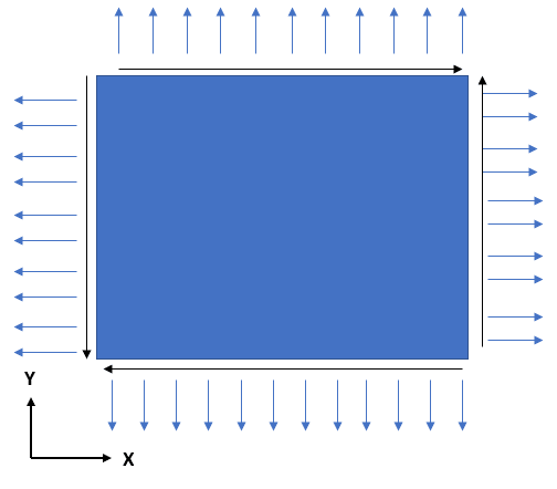
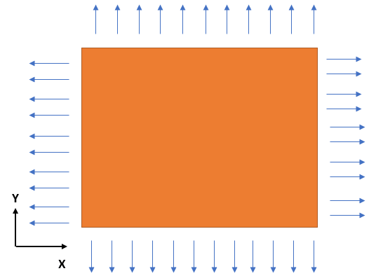
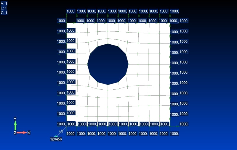
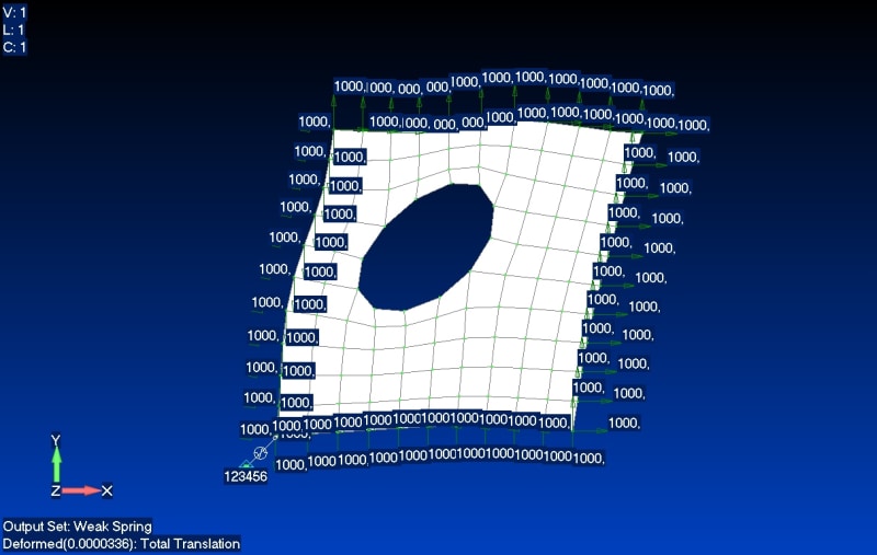
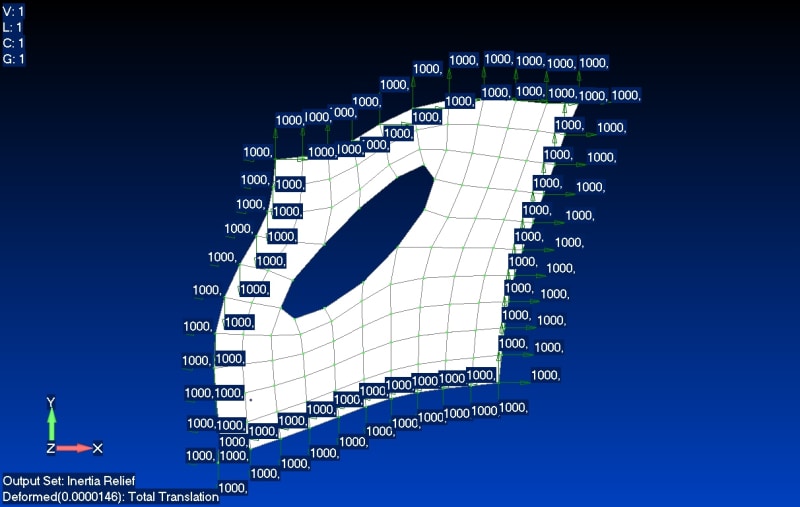
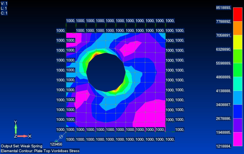
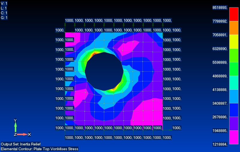
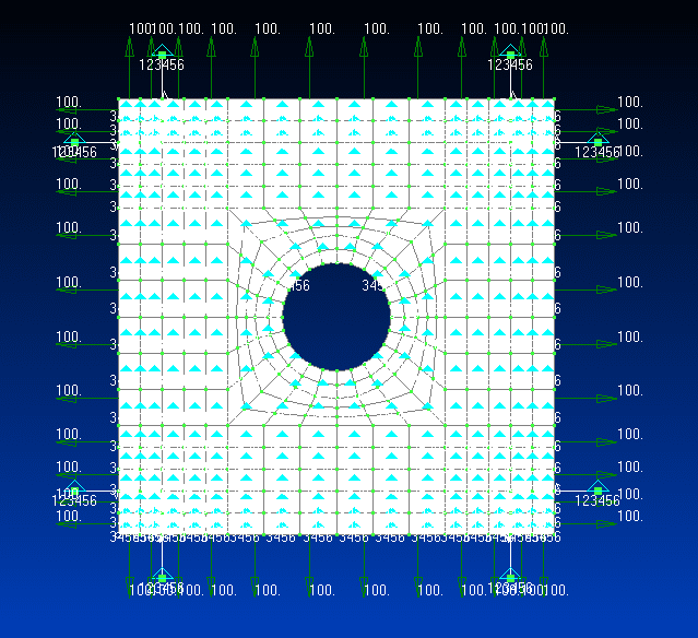
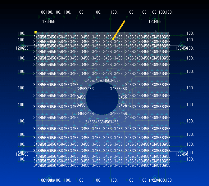
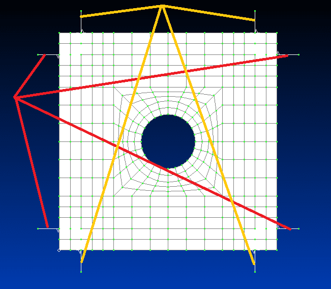
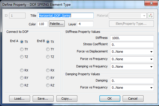
The general approach is OK, but obviously something is off. Instead of using spring elements, try using rod/truss elements. They are similar for this use; just back calculate the k=AE/L (maybe try k=10,000 to 100,000 since k=1,000 may be too small). If that works, then something is incorrect with the spring element inputs. FYI, there are only 3 DOF (1, 2, 3) active for the springs/rods. Beam elements would have 4,5,6 active, but don't use those. The picture associated with the bailout run is not very helpful. Just plot the deformed shape over the original shape (set it to actual scale).
If that still does not work, just use the 3-2-1 approach. For this case, it is just 2-1 (w.r.t corner constraints) since you constrain the plate in the entire z-direction. One corner is constrained in 1,2 and the adjacent corner in just 1 or 2 (depending on the corner). This will be simpler since it seems you are having difficulty with the springs.
The plate should only be constrained in the 3 direction, not 4,5,6. Constraining the entire plate in 3 automatically stops RBM in 4,5. RBM in 6 is stopped by either the springs/rods or the corner constraints.
Side note. You should apply an edge load. The pre processor will calculate the correct forces to apply to each node. The nodes at the end will have half the load as the interior load. This is also why the 3-2-1 approach is just fine, but may give some local peak stresses at the constraints. You can not control the actual load at the constrained corners, you just get what you get (as opposed to the actually intended nodal loads).
Last note: As rb1957 stated, you have more springs than necessary. You only need 2 near one corner and 1 at the other (just as if you were constraining the corners for the 3-2-1 or 2-1 in this case). Just make sure they are in the correct directions to stop 1,2,6 for the plate. It won't matter too much if you have 8 and ensure the spring/rod forces are low, but it is better not to introduce overconstraints.
