Continue to Site

Eng-Tips is the largest engineering community on the Internet

Intelligent Work Forums for Engineering Professionals

  • Congratulations KootK on being selected by the Eng-Tips community for having the most helpful posts in the forums last week. Way to Go!

MSC Patran Composite Question & a Vibration Analysis Question

Status
Not open for further replies.

Burner2k

Aerospace
Jun 13, 2015
193
Hello,
I have a basic question regarding modeling composite laminates using MSC Patran. I need to edit input deck files that I receive from my colleagues and I use MSC Patran to do the same. I use the PCOMP editor and I have asked this question to our MSC seller as well but I am not convinced by their response.

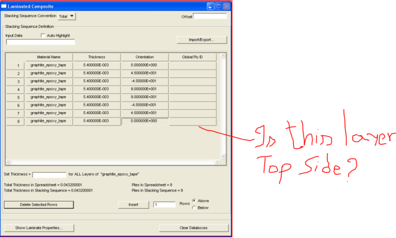
Ref to image below, which side in Patran PCOMP editor represents bottom layup & which top? We may need to play around with some asymmetric layups and thus top & bottom side becomes important.
Capture_pxgo9p.png


Second question I have is with natural frequency. If I am trying to clear the natural frequency of a structure from the frequency of a rotating source, how do I decide the range (min & max of rotating source frequency)? Any thumb rules or sources which I can find such information.
 
Replies continue below

Recommended for you

1) I'd've thought 1 was top ... but it could just as easily be bottom. but play with it ... make a plate, put it in bending, see which ply is in tension.

2) I'll leave to others. I'd've thought you leave a wide berth around the operating frequencies (like 2x) but then you also have to worry about multiples.

"Hoffen wir mal, dass alles gut geht !"
General Paulus, Nov 1942, outside Stalingrad after the launch of Operation Uranus.
 
and so the more knowledgeable "others" have spoken !

I would be careful (scared ?) of some of the surprises that an unsymmetric lay-up may bring.

"Hoffen wir mal, dass alles gut geht !"
General Paulus, Nov 1942, outside Stalingrad after the launch of Operation Uranus.
 
Ply 1 is typically the bottom (z=-t/2) ply.

Of course, just to be annoying, Nastran plate moment sign convention is the opposite of laminated plate theory moment sign convention.

Make a one element test case with +ve Mx applied and sort out the results.
 
here's a question I've had about composite ply lay-ups, and FEA. How does FEA know that a ply is discontinuous ?

if you have a ply runout so the laminate goes from 8 to 7, how does the FEA know that what was ply 8 is now ply 7 ?
if ply 8 was 0deg, and ply 7 45deg on one element and on the next ply 7 has run out so ply 7 is now 0deg ??
Similarly adding plies ??

"Hoffen wir mal, dass alles gut geht !"
General Paulus, Nov 1942, outside Stalingrad after the launch of Operation Uranus.
 
rb1957:

I would assume that a typical formulation for plies involves smeared properties, i.e., plies add to the element bending and in-plane stiffness by integration over the thickness. Organizing numbering and angle of plies consistent with ply properties assigned to the plane surface is then merely a matter of book-keeping in the numerical code.
 
At least in Femap, it GUI clearly shows which side is Top. I went through MSC documentation on Patran & so far I have not come across any content regarding which side is Top or Bottom. I think I will import the input deck in to Femap and find out there.

RB1957, using global ply IDs, one can tell Nastran if a ply is continuous across regions or zones. Global Ply IDs should be inputted manually in Patran but while Apex does it automatically. During post-processing, if a continuous ply is selected, the output contour is shown in applicable region. Of course, one would still have discontinuity in stresses/strains in ply drop off regions (especially if the transition is not modelled).

Typically, how are ply drop off regions handled? It would be difficult to model ply staggering in FEM when we have large number of staggering...lets say if we have 30 plies dropping off to lets say 20. Currently, we are just dropping the plies off abruptly (30 goes to 20 at the boundary...no staggering) and we see a nice stress or strain concentration (surge in values) at the boundary (sudden change in stiffness). Even with stress concentration, we are below allowables and hence not bothering...but sake of information I want to know how more experienced professionals or companies handle.
 
Greglock, thanks for the response on range.
 
thx burner, that makes sense.

Yes, with ply drop off (like at an edge) it's much more abrupt than in practice, particularly core ramps.

"Hoffen wir mal, dass alles gut geht !"
General Paulus, Nov 1942, outside Stalingrad after the launch of Operation Uranus.
 
rb - the dirty little secret is that FEA codes have NO clue about a ply being discontinuous (well, unless someone models the laminate with separate 3D elements for every ply). The stiffness matrix is generated for each element separately using the laminate stack for that element. There is no accounting for the interlaminar stresses at the ply terminations. And for the most part, the is perfectly ok. We have design rules for ply terminations that are based on test data and experience, and they work fine when followed.
 
I took that to mean that was how he was modelling it, but in reality there is the normal staggered drop-off (just too detailed for the model mesh).

"Hoffen wir mal, dass alles gut geht !"
General Paulus, Nov 1942, outside Stalingrad after the launch of Operation Uranus.
 
"guess I just assume the worst" ... Why don't you knock it off with them negative waves? Why don't you say something righteous and hopeful for a change?

(smile, we've all be bashed with the "bat of experience")

"Hoffen wir mal, dass alles gut geht !"
General Paulus, Nov 1942, outside Stalingrad after the launch of Operation Uranus.
 
Status
Not open for further replies.

Part and Inventory Search

Sponsor