Hi,
I have another question regarding Tertiary Datum Feature again.
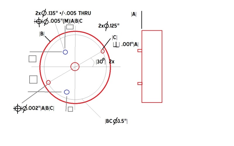
Sometimes, I see a drawing having 2 pins. Most of drawings pointing at one(1) Pin with label |C| and other pin will have True Position...
(Please see attached drawing).
My questions are:
1/ If a design is used one(1) pin for its tertiary datum feature for locking rotation (as shown in picture), then to establish this "locking line/axis" is to connect center of |B| to center of |C| which is pin@30deg. Not center of pin@210deg to pin@30deg. is that right?
I've seen some inspectors connecting center of 2 pins. To me it's not correct because other pin is asked to be checked with using |A|B|C|.
If the locking line/axis is connected from center of 2 pins and if pin@210deg is NOT located at center of a boldcircle 3.5" then other holes would be out of location.
2/ Why does the design use 2 pins. Does it cost more $$$?
Thanks,
Brandon
I have another question regarding Tertiary Datum Feature again.
Sometimes, I see a drawing having 2 pins. Most of drawings pointing at one(1) Pin with label |C| and other pin will have True Position...
(Please see attached drawing).
My questions are:
1/ If a design is used one(1) pin for its tertiary datum feature for locking rotation (as shown in picture), then to establish this "locking line/axis" is to connect center of |B| to center of |C| which is pin@30deg. Not center of pin@210deg to pin@30deg. is that right?
I've seen some inspectors connecting center of 2 pins. To me it's not correct because other pin is asked to be checked with using |A|B|C|.
If the locking line/axis is connected from center of 2 pins and if pin@210deg is NOT located at center of a boldcircle 3.5" then other holes would be out of location.
2/ Why does the design use 2 pins. Does it cost more $$$?
Thanks,
Brandon