Eng-Tips is the largest forum for Engineering Professionals on the Internet.

Members share and learn making Eng-Tips Forums the best source of engineering information on the Internet!

  • Congratulations JStephen on being selected by the Eng-Tips community for having the most helpful posts in the forums last week. Way to Go!

A flow rate question? 4

Status
Not open for further replies.

PhilSham

Mechanical
Joined
Mar 31, 2015
Messages
5
Location
IE
Hi all,
I'm trying to work out the flow rate for a pump to heat a chicken house. The farmer has already laid pipe and wants to size a pump. Its a two pipe system, feed and return with 5 water to air heat exchangers Link. He appears to have the first two in parallel, the next two in parallel and the last one on its own. Water flow-through is given as 1.76 m3/h for the exchanges, should i be aiming at a flow of twice this so that the first 4 get the required flow with the last one getting double?
 
Type 3H or 3V, eh? A rough sketch of the layout with piping and diameters and lengths would be most valuable at understanding the system.

Good luck,
Latexman

Technically, the glass is always full - 1/2 air and 1/2 water.
 
Probably should be sized so that each heater has 1.76 m3/h passing through it. With the arrangement that you mentioned, that would be 3 times.
 
Eh? There are 5 heaters, therefore total flow = 5 x 1.76m3/hr. This assumes they all feed from the same manifold.

You seem to be saying that each set has its own pump? In that case and you want to make each pump the same then yes, 2 x for the parallel units and double flow for the single unit. This is why we need a diagram.

Of course the real issue is how to control and adjust the heaters so that each one get 1.76m3/hr and not , say, 3m3/hr

A diagram with lengths and pipe sizes is essential to work out what the pressure drop will be for the worst case and then add some control valves in the other lines / heaters

Remember - More details = better answers
Also: If you get a response it's polite to respond to it.
 
1 proper sketch > 1,000 words!

Good luck,
Latexman

Technically, the glass is always full - 1/2 air and 1/2 water.
 
Let's do the words first.

OMG%20something%20else.png
 
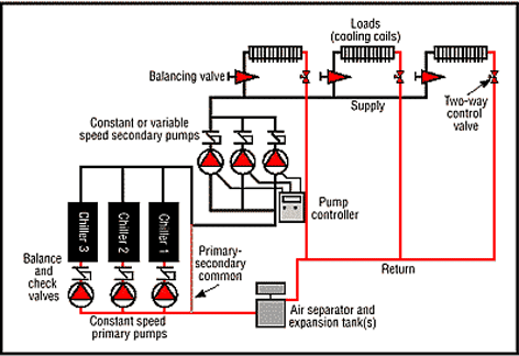
The manufacturer of the heater should be able to provide you with a sketch like this:

BOpEqSysWaterDistributionSystem_2W_erknax.png


The person who decided that 5 heaters is required is the one to ask.
 
Suggestions :

a) Size all supply and return lines with similar psi/100ft.
b) Add an RO on each supply line sized to produce a minimal dp at desired flow and include pressure taps at suitable distances from RO
c) Add a manual gate on each line to throttle to suit

During commissioning, set the hot water flow for each air heater by adjusting the gate on each line to get to target dp across the RO.

Some allowance on total pumping flow may be useful, say 10% of design = 1.1 x 1.8 x 5 = 10m3/hr. Some margin on controlling case dp for the pump would also be useful.


All lines should be liquid primed - add high point vents.

The hot water - air heater coil passes should also be freed from trapped air - a vertical orientation ( as shown in the photo ) makes this difficult.

 
The supply lines to each may be just DN25 at Q=2m3/hr, so an RO on this line may not be convenient.

Another way is based on equal exit temps for hot water from each heater - use a portable IR temperature gun to read off exit water temp by measuring pipeskin temp, and adjust the gate valve to suit.
 
Hi guys, thanks for the info, it's the 3H units that are being used. I drew up a quick sketch of the planned arrangement, pump would be fitted on the start of the feed line.
LittleInch and georgeverghese, i would say your guys are right, it would be 5 times the requirement plus 10% allowance to be safe.
 
 http://files.engineering.com/getfile.aspx?folder=b8480de1-174f-48f2-a161-00d2aafd5fb9&file=img004.jpg
a) Seen the sketch - Would be useful to add an isolation valve on the exit of each unit also for individual unit maintenance
b) Add this throttle valve to each unit ( not to be doubled up as an isolation ) and have it set in a fixed position.
c) How are you going to manage temp control in this chicken shed (1)vary pump flow ( through a supply to return bypass valve) or (2)vary pump speed or (3) vary hot water feed temp
do you intend to automate this

d) What kind of pump is this - flow is low at 10m3/hr

e) Where is the expansion drum / degasser - is the feed nozzle to this at a higher elevation than all the piping and heaters ?

Main risk is air traps in the piping that may create high discharge pressure and choke up your pump

Okay if you are using the horizontal version 3H - check that exit nozzle is at higher elevation than the inlet so air gets to flow out of the coils.

 
All 5 in parallel. Agree, 5X plus safety factor.

Most major pump vendors offer low flow centrifugal pumps. That may be a good place to start.

Good luck,
Latexman

Technically, the glass is always full - 1/2 air and 1/2 water.
 
Agree that the 5 units are in parallel, so the pump should be sized for 5 times. Don't see any need to oversize the pump.

You should have balancing valves and an expansion tank with an air bleed on the high point.
 
You need to make those valves shown decent globe type control valves. The chance of you getting the flow to be within 10% of your rather precise 1.76 m3/h is not worth thinking about but I would size your unit for 5 x flow plus 20% otherwise one unit will end up by accident taking a lot more flow than the others. This won't mean more heat, only that the discharge temperature will be more than the others, but this will starve the others (or more likely the single one at the end) of flow if you're pump isn't man enough.

To set your system up you probably want to do this by checking temperature in and out is equal when all five fans are working.


Remember - More details = better answers
Also: If you get a response it's polite to respond to it.
 
The other way to manage temperature in the shed is to run the circ pump and the heater/fan units on start-stop basis with on - off signals from a shed thermostat - that will save on power. If it is critical to maintain shed temp in winter, you might one to keep a spare pump handy - you might be still be okay if one of the 5 fan / heater units breaks down ? If it isnt too hot, some plastic pipe materials may be good for this also?
 
If you need antifreeze protection, may have to switch out from hot water to either MEG - water mix or propylene glycol - water mix.

Mono ethylene glycol is slightly toxic while PPEG is not, but PPEG - water has a higher viscosity and higher first cost. No flash point concerns with MEG.

For example, a 50% wt MEG - water mix is good down to -25degC or so, but viscosity is much higher than water as we go cooler, so if the pump needs to be started from cold, then the one of the operating cases for head at the pump may be something like 50% of 10m3/hr at startup from cold for more viscous MEG solution.

Other transport properties for MEG solutions will need to be accounted for. Use demin water to make up the solution and the Perry Chem Engg Handbook says add "inhibitor", but it doesnt say what type.


Thanks for all the info, i had left some of the basics out of the sketch, their is an expansion drum on the line and is a coolant not water that will be running through it. High points of the pipework will have air bleeders installed and we will have a valve at each side of the heat exchanger to removal and maintenance. Fans and pump will be thermostatically controlled. I think the exchangers come with flow control valves but can easily add them if they don't.
 
If you are going for MEG - water, and given the tubes on this HX are SS ( doesnt say what grade), chloride stress corrosion cracking risk ( for operating temp >60degC, which is what you have here) is minimised by adding oxygen scavenger to the makeup demin water to mop up the dissolved oxygen - you could use sodium sulphite or a hydrazine based derivative for this.

Presume you are aware that MEG solution rates will need to be higher than 1.8m3/hr to get the same heating loads, and hence unit dp will be higher also. The light duty flow balancing gate valves should do - wont need flow controls. Good luck
 
Most use propylene glycol in these systems; Dowfrost, by Dow Chemical, or equal, with all the appropriate inhibitors, etc. It is common to have the glycol installed with distilled or deionized water, so that the inhibitors will not be consumed by the chemicals in the water. The glycol is added for freeze protection. In closed systems like this, there is little oxygen present, so there is little risk of corrosion.
 
Status
Not open for further replies.

Part and Inventory Search

Sponsor

Back
Top