Navigation
Install the app
How to install the app on iOS
Follow along with the video below to see how to install our site as a web app on your home screen.
Note: This feature may not be available in some browsers.
More options
Style variation
-
Congratulations JStephen on being selected by the Eng-Tips community for having the most helpful posts in the forums last week. Way to Go!
You are using an out of date browser. It may not display this or other websites correctly.
You should upgrade or use an alternative browser.
You should upgrade or use an alternative browser.
Truss Top Chord Lateral Support 1
- Thread starter hoshang
- Start date
- Thread starter
- #41
Hi BA,
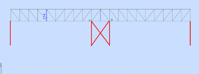
I meant can points A and B in this image be considered as support points?
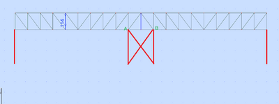
or these points (my A and B) can be assumed as one point so that there would be 3 points of support: one at each end and one at the middle so it can mimic the analysis model (a two-span truss supported by three points)?
I meant can points A and B in this image be considered as support points?

or these points (my A and B) can be assumed as one point so that there would be 3 points of support: one at each end and one at the middle so it can mimic the analysis model (a two-span truss supported by three points)?
- Thread starter
- #43
Yes, that would be possible.Hi BA,
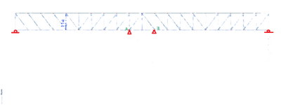
My thought is this
View attachment 15328
analytically maybe represented by this for simplicity (i.e., two hinges and two rollers):
View attachment 15329
Am I right?
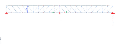
My query is what would mimic this (i.e., two rollers and one hinge):
- Two rollers and one hinge would be possible, but a pinned support would need a stiff column below it, fixed at the base and pinned at the top. A pin can't exist by itself.
- The entire structure would deflect with the column in addition to temperature movement.
- Each truss would span 90' instead of 60', so the trusses would use more steel.
- Erection would be considerably more difficult without a middle truss held in place while erecting the two exterior trusses.
- Thread starter
- #45
post #38
Can you elaborate more on the your red phrase? BTW how would you reference to my posts? I tried it without success.BAretired states:
If there is sufficient clearance for road widths, I suggest the vertical leg of the orange Tee be 2 panels wide. Alternatively the orange truss should be modified, or a different concept should be considered.
No, I will not elaborate! The information you must provide are:post #38
Can you elaborate more on the your red phrase?
- the required vertical clearance under the bridge to allow the passage of vehicles.
- the required width of road.
- the required separation of roads.
Last edited:
- Thread starter
- #47
20ftBAretired said:
- the required vertical clearance under the bridge to allow the passage of vehicles.
45ftBAretired said:
- the required width of road.
12ftBAretired said:
- the required separation of roads.
I meant when you quote my posts:BAretired said:
I do not understand your last two sentences about referencing your posts. What do you mean?

That seems a bit high for vertical clearance. Are 22' high stairs planned at each end of the bridge?20ft
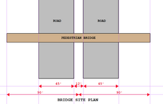
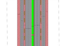
Why are 90' long trusses needed to span across 45' wide roads? Provide a site plan.45ft
- Thread starter
- #50
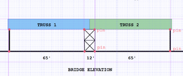
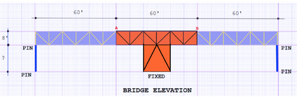
Your query has been answered in an earlier post! The structure below is equivalent to one pin (middle) and one roller each end. But the overall length of trusses does not have to be 180'. it has to be only 65+12+65 = 142'. Two 71' trusses would seem to be sufficient. There is no need to make them continuous; they could each be simple spans with a short cantilever at the middle. Then, if some clown collides with one truss, it can be replaced without disturbing the other.

Last edited:
- Thread starter
- #53
Have you switched from Imperial to Metric measurements? I believe your site plan dimensions are in metres.
hoshang said:
So, how would you support the midspan using a box truss support that would act as one-point support at midspan?
I would not use a one-point support in the middle. I would investigate alternative schemes, but at this time, the arrangement shown on post #52 would be my choice. Trusses 1 and 2 would be simple spans with a short cantilever at one end, possibly at both ends, depending on how the access stairs are to be framed.
With the new information, a reduction of span is possible. See below.
It is important to note that a strong central support is necessary to ensure stability of the structure. Moment each end of Truss #2 can be zero if a pin connection is used or, if preferred, the truss can be continuous throughout.
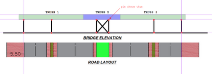
It is important to note that a strong central support is necessary to ensure stability of the structure. Moment each end of Truss #2 can be zero if a pin connection is used or, if preferred, the truss can be continuous throughout.

- Thread starter
- #56
Hi Ba,
Appreciate your response.
A few concerns:
1- The architect didn't accept this configuration:
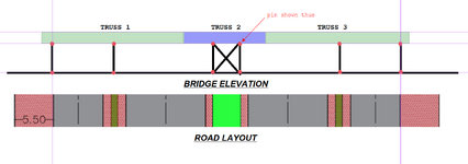
He accepted this configuration:
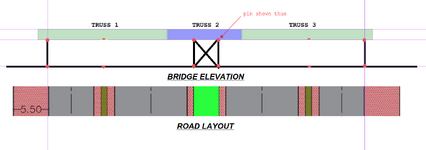
2- Would you consider the truss as being supported on one-point support:
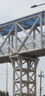
or would you consider the truss as being supported on two-point support:
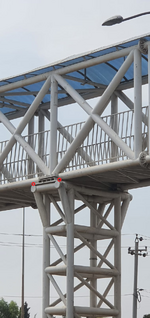
or would you consider the truss as being supported on linear support:
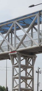
Appreciate your response.
A few concerns:
1- The architect didn't accept this configuration:

He accepted this configuration:

2- Would you consider the truss as being supported on one-point support:

or would you consider the truss as being supported on two-point support:

or would you consider the truss as being supported on linear support:

Last edited:
Hi Ba,
Appreciate your response.
A few concerns:
1- The architect didn't accept this configuration:
That does not surprise me!
View attachment 15832
He accepted this configuration:
Okay...it's only money!
View attachment 15833
2- Would you consider the truss as being supported on one-point support:
It is theoretically possible, but the column or box truss support would need to be extremely stiff to resist horizontal forces parallel to the bridge from people moving and wind, but primarily from seismic forces. Also, repair of such a bridge after a collision on any part of it results in the shut down of the entire structure rather than confining it to a more local area. I consider it a very bad idea.
Two point support would be slightly better, but not the way you are showing it. The column (or box truss) should be rigidly connected top and bottom.View attachment 15834
or would you consider the truss as being supported on two-point support:
Last edited:
....A few concerns:
1- The architect didn't accept this configuration:
....He accepted this configuration:
So how do these conversations with the architect go?
"Dear Mr. Architect, my sub-consultant who works for free at eng-tips.com suggested....."
Kudos to BA, man. Holy cow.
Thanks, dold.
The architect rejects a scheme which I believe to be a substantial cost saving and accepts a very similar design without exploring comparative costs.
The Engineer of Record is pushing the design even further by encouraging a configuration which significantly increases construction cost but, more importantly, creates a huge problem in maintenance and repair in the aftermath of a potential future collision with road traffic.
Iraq does not have a building code of its own, and so far as I know, has not officially adopted one. I'm not sure what kind of foot traffic is expected, but the bridge is in the order of 10' (3m) wide. Perhaps the most severe live load could occur with an army crossing over. Hopefully, soldiers would break step while on the bridge. Seismic forces are unknown at present, but they would need to be taken into account.
Last edited:
Similar threads
- Locked
- Question
- Replies
- 7
- Views
- 1K
- Locked
- Question
- Replies
- 9
- Views
- 2K
- Replies
- 3
- Views
- 3K
- Locked
- Question
- Replies
- 14
- Views
- 8K
- Question
- Replies
- 20
- Views
- 7K


